
home-made light-operated camera trigger
This device employs a dual-beam triggering mechanism, enhancing the precision of capturing fast-moving subjects by minimizing the area in which motion is detected. The integration of two sensors, each with adjustable sensitivity, allows for fine-tuning the response to light interruption, which is crucial for achieving high-quality images of fleeting moments. The use of LED lamps or laser pointers as light sources facilitates effective operation even in low-light conditions, making the device versatile for various applications.
The circuitry is designed to ensure reliable operation, with visual indicators (LEDs) providing feedback on the device's status. The output-enable switch and confirmation LEDs allow users to monitor the system's readiness to trigger the camera or flash, ensuring that the setup is functioning correctly before attempting to capture images.
For users with varying levels of electronics experience, the device can be assembled with relative ease, provided that proper attention is given to the circuit diagram and component specifications. The inclusion of alternative components, such as phototransistors, demonstrates the flexibility of the design, allowing users to adapt the device to their specific needs.
In summary, this motion-triggering device represents a cost-effective and customizable solution for capturing rapid movements in photography, suitable for both amateur and professional applications. Its design encourages experimentation and modifications, making it a valuable tool for those interested in high-speed photography.This device is used to photograph moving objects by triggering a camera or flashgun when one or two light beams are interrupted. It was designed to capture insects in flight, but can also be used for projectiles and anything else that moves too fast or irregularly to be photographed by hand.
It cost around $30 to build, and was used to make The Ba rista Collection. There are several commercial triggers available (a good example is The Time Machine ), but they all have a single beam that fires the camera when interupted, anywhere along its length, whereas this device has the option of having a second beam perpendicular to the first, so that the triggering area is much smaller, resulting in fewer out-of-frame subjects. Plus it`s a lot cheaper, and can be modified to perform more specialised tasks. You can see the circuit diagram here. Putting it together probably needs some experience in electronics, and if you find it too ambitious, try the CamTrigJunior.
If you have trouble finding the IPL530 (DAL), try these guys, or replace that part of the circuit with a phototransistor as used in CamTrigJunior. To use the trigger, connect the sensor cable to the 8-pin DIN socket (11), and position the sensors in an appropriate place.
Then shine a light source at each of the sensors, preferably with a fairly narrow beam width. LED lamps work well if the background light levels are low, and these can be powered by plugging into socket 12 of the box. Otherwise pocket laser pointers are excellent sources. Now adjust the sensitivity of sensor A (2) so that with the beam uninterrupted, the red trigger-confirmation LED (4) is just illuminated.
Interrupting the beam should then make the LED go out. If it does not, turn the dial anti-clockwise a little more, whilst still keeping the LED lit. If the LED does not light regardless of the position of the dial, a brighter (or better aimed) light source should be used. Once adjusted, decide whether you want to use a second, intersecting beam. If not, turn the sensitivity control for sensor B (3) fully anti-clockwise, so that it detects no light and behaves as though it is always interrupted.
If you do want a second beam, set it up perpendicular to and intersecting the first, in such a way that when your subject interrupts both beams simultaneously, it is centered in the camera viewfinder and in the plane of focus. Adjust the sensitivity control for sensor B (3) in the same way as you did for A. Now when both beams are interrupted at the same time, you will see the yellow trigger-confirmation LED light briefly.
If the output-enable switch (8) is down, the green output-confirmation LED (10) will also light. Now you can plug your camera or flash into socket 13. The flash cable should fire any flashgun in manual mode, or one with a built-in automatic exposure sensor on the flash. TTL flash operations will not work. To use the flash mode, the camera shutter must be left open in total darkness while waiting for the trigger.
This means either very dark surroundings (such as a bat cave), or expectation of fairly rapid triggering (such as a box containing a flying insect). To fire a camera it must have a connection which needs to be short-circuited to fire the shutter. I use the 2. 5mm socket on the motordrive of my Olympus OM-4, and would hesitate to plug it in to any other camera without checking the technical specifications.
To trigger the Nikon D70 you will need to make a switch to connect to the remote control (ML-L3), such as described here, and will need to switch on the strobe function with the strobe frequency knob dialed fully clockwise, so that the camera is triggered every 13 minutes regardless of beam interruption, thus ensuring that the reomte-control function on the camera does not time-out. There is also a delay control (not yet shown in the picture of the box), which is enabled with switch (16) and adjusted with dials (17).
This allow 🔗 External reference
Related Circuits
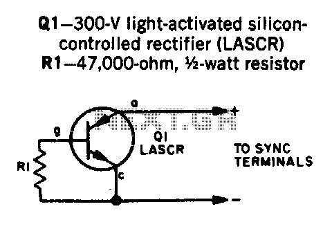
Transistor Q1 is a light-activated silicon-controlled rectifier (LASCR). The gate is activated by light entering a small lens integrated into the top cap. To operate, provide a 6-inch length of stiff wire for the anode and cathode connections, and...
The built-in flash of digital cameras is intended for indoor photography. At distances greater than five meters, the light output is often insufficient for satisfactory images. Many cameras lack a hot shoe for an external flash, necessitating the use...

The camera rotator circuit uses a 2716 EPROM to store a table of logic values that control the motor driver (H-bridge) circuit. The EPROM data is shown in the schematic. By using the EPROM, a large number of discrete...
The circuit consists of a light metering circuit and a flash circuit, as illustrated in the accompanying image. It is designed for use with integrated cameras such as POPTICS, Franka X-500, and WIZEN-860S. The circuit includes the following components:...
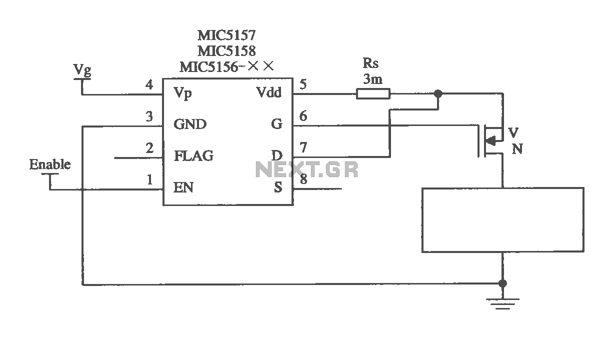
The MIC5156 is a device that incorporates a current limiting function, allowing it to handle high output currents. It can operate with or without a switching regulator circuit. The S terminal is left vacant, and a 16V Zener diode...

The CA 3088 is utilized as a versatile Schmitt trigger. The magnitude of the hysteresis levels is determined by the current (Ia) flowing out of the amplifier's output and through resistor R2. An increase in Ia results in an...