
Homemade disinfectant circuit
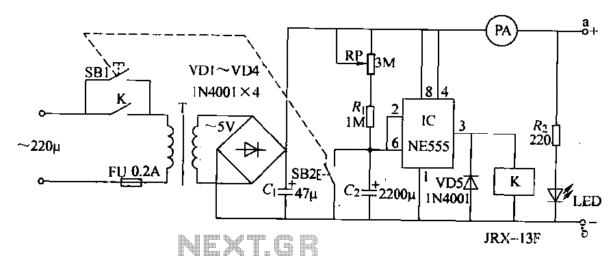
The operation begins when the control buttons (SB1 and SB2) are pressed, allowing the 220V AC voltage to be transformed by the transformer (T) and rectified by diodes (VD1 to VD4). This process generates a 5V DC voltage, which is applied to the electrodes (A and B) in the electrolysis container filled with brine, with the current limited by resistor (R). The LED lights up upon pressing the buttons. The timing control circuit receives power when SB2 is pressed. When SB2 is released, the integrated circuit (IC) output goes low, causing relay (K) to activate and keep the power supply connected, ensuring the circuit remains powered. The timing circuit starts charging, and as the voltage across capacitor (C2) rises to 8V or more, the IC output flips, deactivating relay (K) and disconnecting the AC power supply, thus ending the electrolysis process. The distance between electrodes A and B can be adjusted to optimize the current, which typically operates around 5A.
The circuit is designed to efficiently produce sodium hypochlorite through the electrolysis of a saline solution. The timing control mechanism allows for precise control over the duration of the electrolysis process, which is critical for ensuring the effective generation of the disinfectant. The integration of components such as the rectifier bridge and filter capacitor ensures stable DC output, while the relay provides a practical means to control the power supply based on the timing circuit's status. The use of an ammeter allows for monitoring the current flowing through the system, which is essential for maintaining the desired electrolysis conditions. Overall, this circuit design provides a practical solution for generating a useful disinfectant for various applications.Homemade disinfectant circuit of the present example describes the electrolytic salt solution method to produce sodium hypochlorite (NaCk "disinfectant can be used for students living supplies disinfection. (1) The circuit disinfectant generator circuit from the power circuit and the timing control circuit composition, as shown. the power supply circuit by the control buttons SB1, fuse FU, power transformer T, rectifier bridge VDJ ~ VD4, filter capacitor Ci, current limiting resistor Rz, power indicator light-emitting diode LED and ammeter PA components.
Timing the control circuit from when base integrated circuit IC, potentiometer resistor RI ,, brother, capacitors Island, the control button SB2 diode VD5 and relays K composition. (2) works press of the control button SB (SB1.SB2 linkage), the AC 220V voltage by T buck, VD1-VD4 Cl rectification and after crossing the filter to generate a DC voltage 5v, all the way through the ammeter PA applied to the electrodes a, the b, in the container brine electrolysis I limit all the way down through R after pressing LED lights; the other way as the timing control circuit power supply.
when the contact is turned off SB2, Ic's feet and feet @ goes low, feet high output, K pull-power station its normally open contact connected to the power supply through t lock (power remains on state s after release). then by R and G RP to charge the timing circuit starts timing, so the IC feet and foot voltage constantly @ rise when the voltage across the charge c2 to 8V or more and .Jc circuit flip, which pin output low, K release, K normally open charm points off the AC input power supply circuit is disconnected, making disinfectant (electrolysis of saline) process is ended.
increased electrode electrodes a and b, the distance can be reduced as a positive current (operating current of about 5A to).
Related Circuits
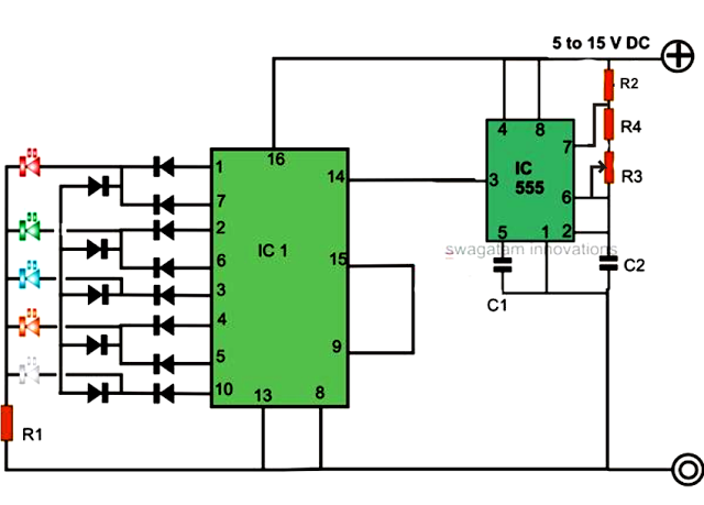
An LED light chaser circuit is an electronic configuration designed to illuminate a group of LEDs in a predetermined sequence. A commonly used integrated circuit (IC) for creating this type of LED sequencer circuit is the 4017. This IC...
The modular Portable Mixer design presented on these web pages has gained popularity among many amateurs. However, some users have requested a simpler device specifically for mixing mono signals. This revised design aims to meet those requirements, incorporating three...
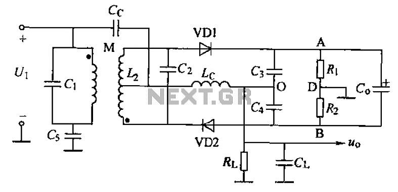
A common phase frequency detector can be categorized into mutual coupling and capacitive coupling frequency discriminators based on their coupling methods. The improved mutual coupling ratio discriminator circuit is illustrated in the figure, utilizing a 2AP9 diode. The phase...
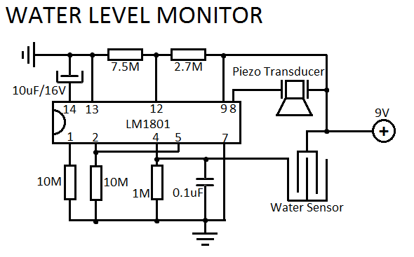
This simple water level sensor circuit monitors the presence of water in a specific location or container. The circuit activates an acoustic alarm when it detects water. The water level sensor circuit typically consists of several key components, including a...
This document describes a 100 Watt inverter circuit that utilizes a minimal number of components. The circuit employs the CD 4047 integrated circuit (IC) from Texas Instruments to generate 100 Hz pulses, along with four 2N3055 transistors that drive...
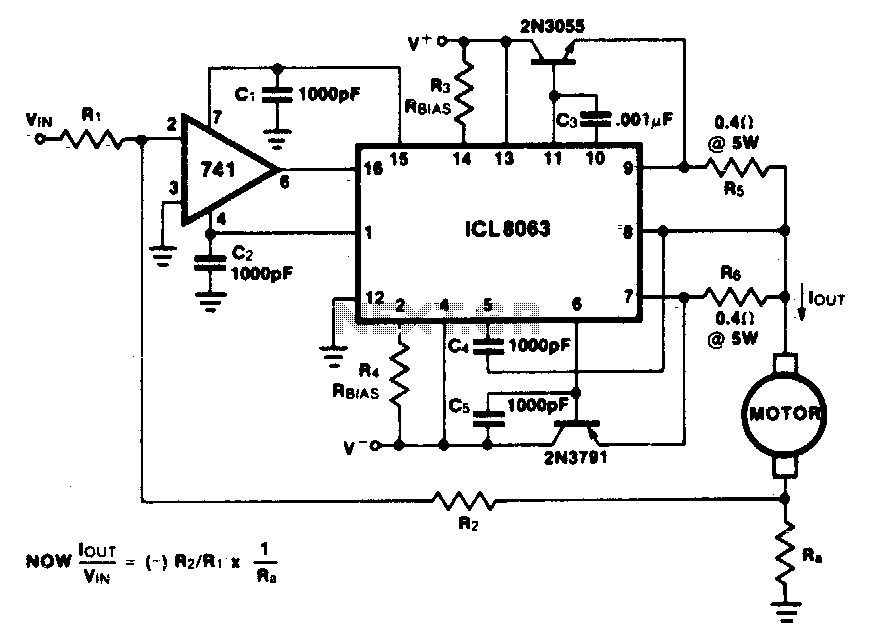
This minimum device circuit can be used to drive DC motors where there is some likelihood of stalling or lock-up. If the motor locks, the current drive remains constant, and the system does not destroy itself. This circuit is designed...