
Egg Timer
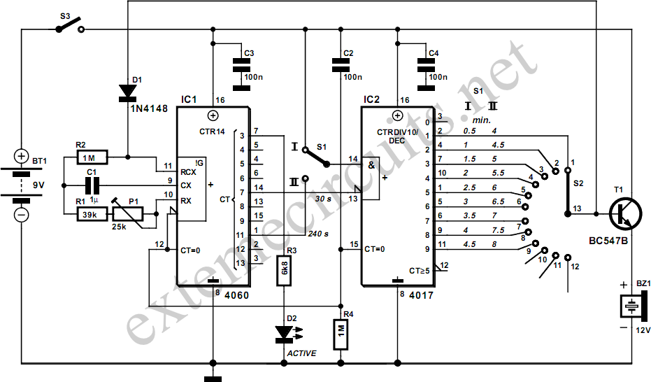
The egg timer circuit employs a straightforward design that effectively utilizes two integrated circuits from the 4000 series: the CD4040 and the CD4017. The CD4040 functions as an oscillator and counter, generating clock pulses that drive the CD4017 decimal counter. This combination allows for the creation of programmable timing intervals suitable for various applications, particularly for timing tasks such as boiling eggs. The use of a rotary switch enables the user to select between two timing ranges, enhancing the versatility of the device.
The oscillator is configured using a resistor-capacitor (RC) network, which allows for a lower frequency output compared to standard crystal oscillators. This flexibility is crucial for achieving the desired timing intervals, as the circuit is designed to produce accurate timing without the need for complex microcontroller programming. The oscillator operates at a frequency of approximately 8.5333 Hz, providing a clock pulse every 30 seconds to the CD4017 counter.
The CD4017 counter is capable of counting up to ten, with each output corresponding to a specific time interval. The first output is not utilized due to its state after a reset, while subsequent outputs represent increasing time intervals. The two ranges provided by the rotary switch allow for timing intervals from 1 to 4.5 minutes in one range and 4.5 to 8 minutes in the other.
The buzzer serves as the signaling device, activating when the selected timing interval is reached. The circuit design includes an emitter follower configuration to drive the buzzer, ensuring adequate current flow while maintaining low power consumption. The inclusion of an LED indicator provides visual confirmation of circuit activity, enhancing usability.
Overall, this egg timer circuit exemplifies an efficient, low-power design that leverages basic electronic components to achieve reliable timing functionality without the need for complex microcontrollers. The straightforward design and use of widely available components make it an excellent project for both educational purposes and practical applications.This egg timer, which is both simple and functional, shows once again that it is not essential to use a microcontroller for everything these days. The circuit consists of only two ICs from the standard 4000 logic family, a multi-position rotary switch and a few individual components.
The combination of a 4040 oscillator/counter and a 4017 decimal counter is certainly not new, but it is an ideal combination for timers that are required to generate long intervals that can be programmed in steps. The circuit can be directly powered from a 9-V battery, without using a voltage regulator. The signalling device is a 12-V buzzer, which generally works quite well even at a much lower voltage.
We won`t explain the operation of the two ICs here; if you would like to know more about this, we recommend consulting the device data sheets. The RC configuration has been selected for the oscillator circuit of the 4060, since the frequencies of standard crystals and resonators would be too high (even 32.
768 Hz is much too high), making it impossible to achieve the desired times. With an RC oscillator, it`s also easier to modify the times to suit our purposes. For instance, if the oscillator frequency is reduced by a factor of two, we obtain a range of 1 to 16 minutes in steps of 1 minute. The range is split into two by taking advantage of the fact that the 4017 has an AND gate at its input (with an inverted input).
The two ranges overlap by two steps. The oscillator has been dimensioned such that the 23 divider output (pin 14) has a period of 30 seconds, so IC2 receives a clock pulse every 30 seconds. This means that the oscillator frequency must be set to 8. 5333 Hz. The first output of IC2 is active after a reset, so it cannot be used. If S1 is in position I, pin 14 of IC2 is connected to the positive supply line. This input is used as an enable input. Directly after the first pulse from the 4060, the second output of IC2 goes high (which means after exactly half a minute).
The sub-sequent outputs become active in turn at intervals of one clock pulse, and thus generate the states for 1 to 4. 5 minutes. In the second range (II) of S1, the enable` pin of IC2 is connected to the 212 divider output of the 4060 (pin 1).
This output goes high 4 minutes after the reset (which is why it is labelled 240 s`, instead of the period time of 480 s). Since the 4060 is an asynchronous counter, this output goes high a short time after the 23 output goes low.
This delay provides the proper condition for an extra clock pulse for the 4017. The outputs of the 4017 will thus count upwards once. This means that the second output will become active after 4 minutes, with the rest of the outputs becoming active after 4. 5 to 8 minutes. The desired timing interval is selected using switch S2. The output of S2 is connected directly to emitter follower T1, which energizes the buzzer when the level on the wiper of the switch is high.
At the same time, the counter of IC1 is disabled via diode D1 by forcing the oscillator input high. The buzzer thus remains active until the circuit is switched off. The first counter output of the 4060 is connected to an LED (D2), which indicates that the circuit is active and the battery not yet exhausted. The blinking rate is approximately 0. 5 Hz. The current through the LED is set to a modest 1mA, since this current represents the majority of the current drawn by the circuit.
This ranges from 0. 5 to 1. 5 mA, with the average current consumption being approximately 1mA while the timer is running. The buzzer used in our prototype increases the current to around 13 mA when it is energized, but this naturally depends on the actual type used. In principle, the circuit will work with any supply voltage between 3 and 16 V. However, the actual supply voltage should be taken into account in selecting the buzzer. The value of the supply voltage also has a small effect on the time interval, but in practice, the deviation proved to be less than 5 percent - which is not likely to matter too much to the eggs.
🔗 External reference
Related Circuits
How many individuals have experienced legitimate issues with the 555 timer? It can be inferred that these problems often involve the reset line, specifically pin 4, which must be set high before operation. The 555 timer IC is a versatile...
Numerous effective In-System Programming (ISP) designs are available for 8-bit AVR microcontrollers. However, many of these designs necessitate a pre-programmed microcontroller, presenting the "Chicken or Egg" dilemma: programming microcontrollers requires having one that is already programmed. While solutions utilizing...
This timer is designed for individuals seeking to achieve a tan while minimizing excessive exposure to sunlight. A rotary switch adjusts the timer based on six classified photo-types. A photoresistor modifies the preset time according to the brightness of...
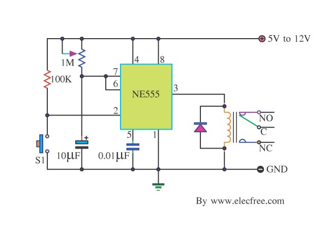
Many friends take an interest in the circuit involving the highly popular IC 555, which is an integrated circuit. This circuit sets the time in a basic manner. The IC 555 timer is a versatile and widely utilized component in...
The purpose of this circuit is to power a lamp or other appliance for a specified duration (30 minutes in this case) and then automatically turn it off. This functionality is particularly useful for reading in bed at night,...
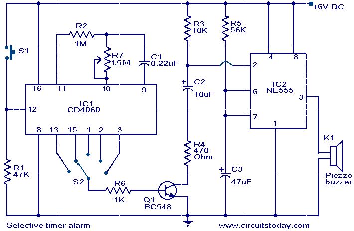
The following circuit illustrates a Selective Timer Alarm Circuit based on the 4060 Integrated Circuit (IC). Features include an automatic turn-off mechanism for the alarm after a specified duration. The Selective Timer Alarm Circuit utilizes the 4060 IC, which serves...