An amplifier designed to complement an antique Meissner AM High Fidelity tuner that has been restored. Upon completion, the amplifier delivered such impressive sound quality that it became the preferred choice for listening to CDs while working. The only new components purchased were resistors, capacitors, and an aluminum chassis from Hammond, while the remaining parts were sourced from disassembled chassis and eBay auctions. The total investment is estimated at around $50, with approximately one week spent on building, rebuilding, tweaking, and experimenting. The output transformer was salvaged from a Hammond church organ chassis purchased on eBay, which also included two 6L6 tubes, two 6SL7s, and a couple of 6SN7s. A 5V4 rectifier was acquired for $6, and the power transformer was obtained from a fortunate eBay win that included two transformers for $10. The signal from one or both input jacks is combined with a resistor network consisting of two 100K resistors and a 50K gain control potentiometer. The signal is amplified by a 6SL7 twin high mu triode configured in parallel to reduce noise and provide a feedback point for global feedback. The gain is minimized due to the absence of a bypass capacitor around the cathode resistor, along with the implementation of global and local feedback through a 470K resistor connected to the plate of the input triode of the Schmidt phase inverter. The output is coupled to the grid of the first triode in the Schmidt phase inverter via a 0.005 µF capacitor; larger coupling capacitors resulted in distortion due to a phenomenon known as "blocking." A 50K resistor to ground in the cathode of the phase inverter serves as a constant current source, allowing the plate resistors to maintain the same value. Values exceeding 50K would elevate the cathode voltage beyond the heater-cathode rating of the 6SL7. The output signals from the phase inverter are nearly identical in amplitude but inverted in phase. No distortion was detected on the oscilloscope at the plates of the inverter with a 0.5-volt input signal, tested using a restored Heathkit sine/square wave generator. Local feedback was introduced through a 470K resistor connecting the first phase inverter plate to the input amplifier plate. The output stage comprises two metal 6L6 beam power tubes arranged in a push-pull configuration, with a fixed bias of -24V applied to the grids via 100K grid resistors. This bias is slightly higher than the RCA tube manual recommends, but it results in cooler operation and reduced power consumption when no signal is present. Increasing the bias by a couple of volts added negligible distortion. The tubes are biased for Class AB1 operation, allowing for cutoff on peak negative grid voltage excursions while preventing grid current during peak positive excursions. Two 0.003 µF capacitors were utilized for stability; local feedback from the plates of the 6L6s to the plates of the 6SL7 phase inverter using a 470K resistor was initially tested but found to be less effective than the capacitors, which improved stability and reduced gain at frequencies outside the audio range. The output transformer, sourced from a dismantled Hammond church organ that originally housed two 6L6s in a push-pull setup, is compatible with the amplifier design. The specific impedance of the transformer is unknown, but it is presumed suitable since it was originally used with 6L6s. Although global feedback was not part of the original design, extensive experimentation led to the discovery of feedback network values that achieved a flat response without stability issues. For testing, a five-ohm, 25-watt resistor was connected to the speaker terminals. With the specified feedback values and a resistive load, the response was flat from 20 Hz to 20 kHz at an output of 18 watts. When connected to an RCA eight-ohm center channel speaker, featuring two bass/midrange speakers and a ribbon tweeter, along with an eight-ohm subwoofer, the response exhibited a 3 dB rise at 35 Hz, followed by a nominal drop.An amplifier to go with an antique Meissner AM High Fidelity tuner that I had restored. But by the time the amp was finished it sounded so good that it has become my amp of choice for listening to CDs while working in the shop. The only parts purchased new were the resistors, capacitors and an aluminum chassis from Hammond. I made use of parts that had accumulated from parted out chassis and Ebay auctions. I estimate that there is around $50. 00 total invested with about a week of building, rebuilding, tweaking and experimentation. The output transformer is from a Hammond church organ chassis from Ebay that also netted two 6L6 tubes, two 6SL7s and a couple of 6SN7s. I got the 5V4 from Ebay for $6. 00. The power transformer also came from a lucky Ebay win in which I got two transformers for $10. 00. The signal from one or both input jacks is combined with a resistor network consisting of two 100K resistors and a 50K gain control pot.
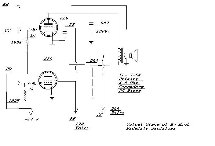
The signal is amplified by the 6SL7 twin high mu triode connected with elements in parallel for low noise and to provide a feedback point for the global feedback. The stage has very little gain due to there being no bypass capacitor around the cathode resistor, global feedback and local feedback through the 470K resistor from the plate of the input triode of the Schmidt phase inverter.
The output is passed to the grid of triode one of the Schmidt phase inverter by a. 005 uF capacitor. I found that any larger coupling capacitor here produced distortion by a phenomenon known as `blocking`. The 50K resistor to ground in the cathode of the phase inverter is large enough to provide a `constant current` source and allows the plate resistors to be the same value.
Any value larger than 50K raises the cathode voltage above the heater-cathode rating of the 6SL7. The output signals are virtually the same amplitude but inverted in phase. I could detect no distortion on the scope at the plates of the inverter with a. 5 volt input signal. (For testing, I used a Heathkit sine/square wave generator that I have restored. ) However, I added local feedback by using a 470K resistor between the first phase inverter plate and the input amplifier plate. The output is two metal 6L6 beam power tubes connected in a push pull arrangement. Fixed bias of -24V is applied to the grids through the 100K grid resistors. This a little more bias than the RCA tube manual calls for but the tubes run cooler and use less power with no signal applied.
I found very little or no distortion was added by upping the bias by a couple of volts. The tubes are biased for class AB1 which means there may be cutoff on peak negative grid voltage excursions but no grid current may flow during peak positive grid voltage excursions. I found that the two. 003 capacitors were needed for stability. I first tried local feedback from the plate of the 6L6s to the plates of the 6SL7 phase inverter using a 470K resistor but found the capacitors provided better stability and lowered the gain for frequencies out of audio range.
The output transformer came from a parted out Hammond church organ that had two 6L6s in push pull. (The chassis had a 6L6GC and a 6L6GB installed when I got it. ) I don`t really know what the impedance is but figured it should work since it was originally used with 6L6s. I had planned to not use global feedback but experimented a little (really a lot:) and found some feedback network values that produced a flat response with no stability problems.
For testing I connected a five ohm 25 watt resistor to the speaker terminals. With the feedback values in the schematic and with a resistive load the response is FLAT from 20 Hz to 20K Hz at 18 watt output. With an RCA eight-ohm center channel speaker consisting of two bass/midrange speakers and a ribbon tweeter and an eight ohm sub woofer connected the response rises about 3db at 35 Hz, drops to nominal a
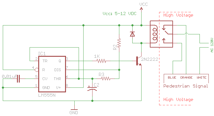
The signal consists of three wires: common, "walk," and "don't walk." This document outlines the operation of the unit's countdown feature. The information and examples provided here are applicable to other models and brands of signals. The signal was...
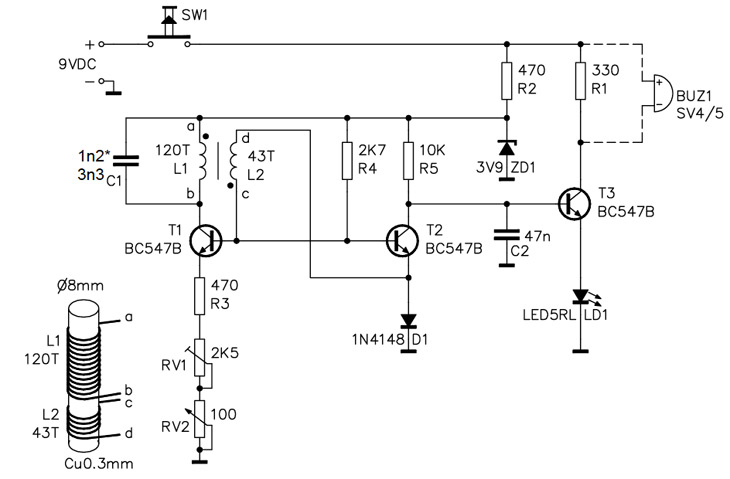
A simple home project can quickly become problematic if it encounters electric cables, gas, or water pipes, or the central heating system. Using a metal detector allows one to check for metal objects within walls, ceilings, or floors beforehand....
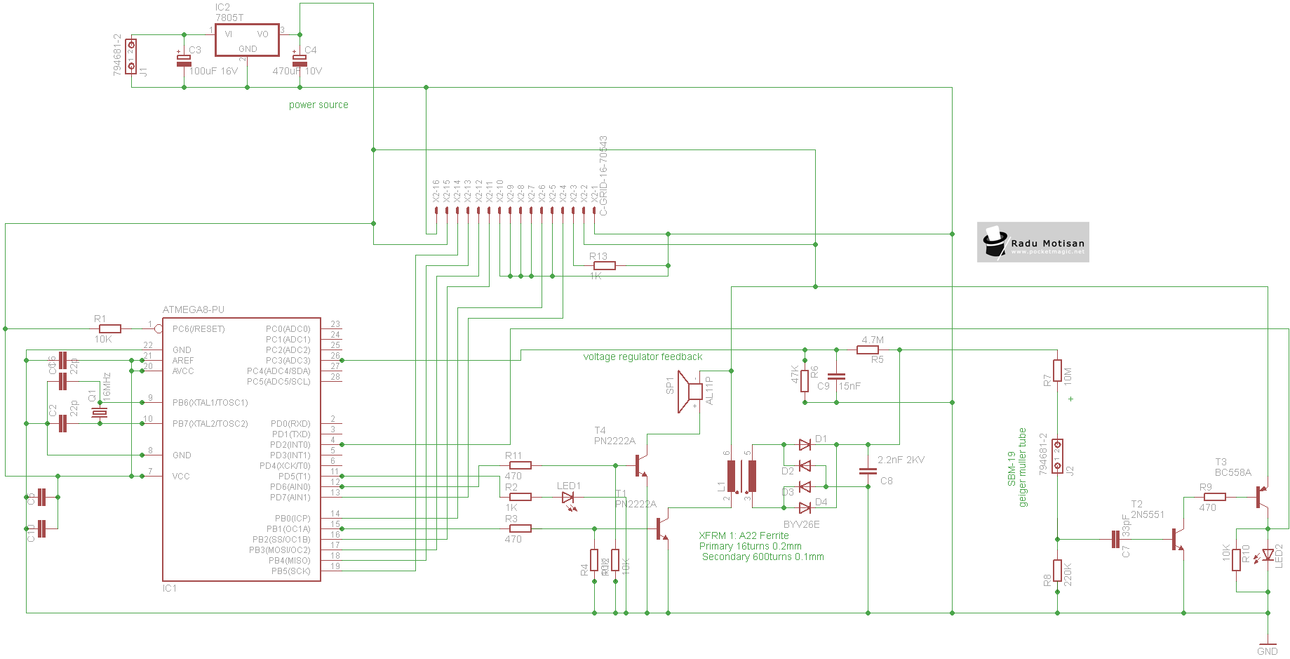
An efficient and stable construction for radiation dosimetry needs. The design centers around the Atmel Atmega8 microcontroller and a Russian Geiger Muller tube, specifically the CTC-1 tube for high gamma doses. The dosimeter is compatible with various tubes including...
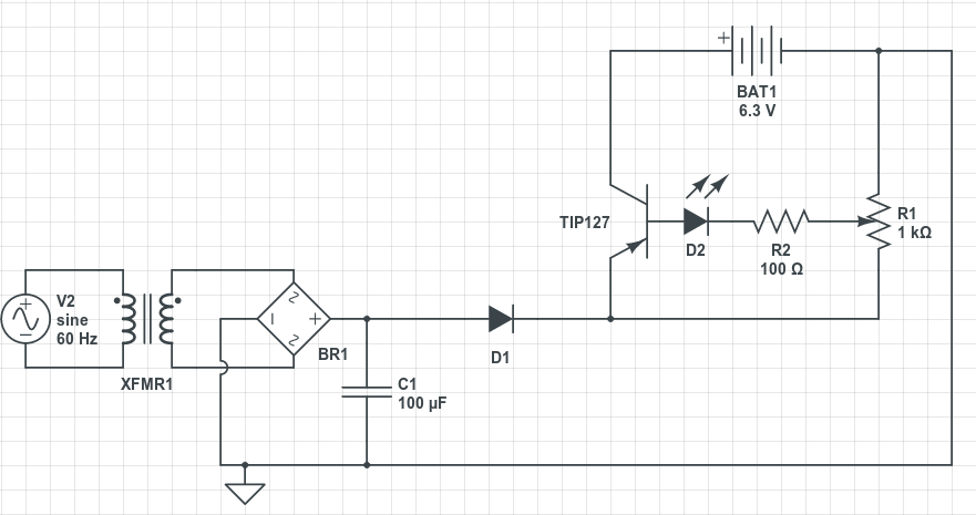
The circuit serves an educational purpose, necessitating simplicity. The construction will utilize only components that are already available, including a variety of resistors, capacitors, transistors, and no integrated circuits (ICs).
The circuit is designed to demonstrate fundamental electronic principles through...
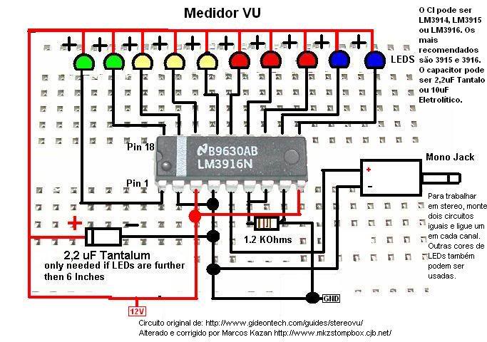
A post related to a do-it-yourself project for creating a VU meter and homemade rhythm lights that are easy to assemble.
The project involves designing and constructing a visual audio level meter (VU meter) that responds to sound levels, as...
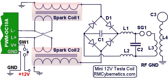
The DIY Plasma Gun is a compact, homemade Tesla Coil gun powered by an 18V battery. It features a specialized plasma discharge terminal capable of emitting ionized gas and flames. The entire system is housed within the casing of...
We use cookies to enhance your experience, analyze traffic, and serve personalized ads.
By clicking "Accept", you agree to our use of cookies.
Learn more