
Honda Civic LX 1990 Control Wiring
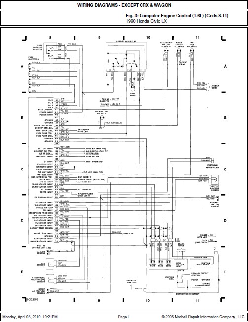
The wiring diagram for the 1990 Honda Civic LX serves as an essential reference for understanding the electrical systems and connections within the vehicle. The Computer Engine Control section, positioned in grids 8-11, illustrates the circuitry associated with the engine management system, including connections to various sensors, actuators, and the engine control unit (ECU). This section is critical for diagnostics and troubleshooting of engine performance issues.
In grids 20-23, the wiring for the Steering Column and A/C Heat systems is detailed. This includes the wiring for the ignition switch, steering wheel controls, and the air conditioning system components. Proper understanding of this section is vital for repairs and modifications related to steering and climate control functions.
The Instrument Cluster, Gear Selector, Defog Switch, and Dome Light are depicted in grids 24-27. This portion of the diagram highlights the connections for dashboard indicators, gear shift position signals, defogger activation, and interior lighting. Each component is interconnected, and any malfunction in this area can affect the overall functionality of the vehicle's interior systems.
Overall, the wiring diagram is a comprehensive tool for technicians and engineers, enabling effective troubleshooting, maintenance, and modifications to the electrical systems of the 1990 Honda Civic LX. Each grid provides a clear representation of the wiring layout, facilitating the identification of components and their respective connections.Here the Honda Civic LX 1990 car wiring diagram document. The document containing the diagram of: Computer Engine Control (1.6L) (Grids 8-11) Steering Column, A/C Heat (Grids 20-23) Inst Cluster, Gear Select, Defog Sw, Dome Lt (Grids 24-27).. 🔗 External reference
Related Circuits
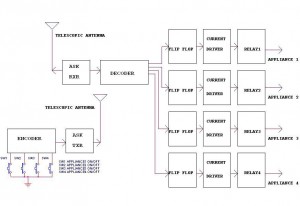
This circuit illustrates a remote control circuit diagram using RF technology without the use of a microcontroller. Features include a simple remote control circuit that operates via radio frequency. The remote control circuit operates by transmitting signals through radio waves,...
Often, people attempt to control DC motors with a variable resistor or variable resistor connected to a transistor. While the latter approach works well, it generates heat and hence wastes power. This simple pulse width modulation DC motor control...
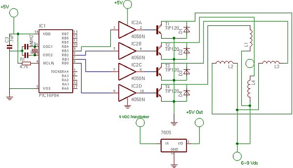
The controller uses one or more ordinary silicon diodes as a sensor, and uses a cheap opamp as the amplifier. I designed this circuit to use 12V computer fans, as these are now very easy to get cheaply. These...
This circuit illustrates the power supply wiring diagram for the Nissan 300ZX, a sports car known as the Fairlady Z. Components include the lighting switch, ECCS, and fuse. The power supply wiring diagram for the Nissan 300ZX is essential for...
Since completing the degree in April, there has been a pursuit for employment. The search has been gradual, but there is optimism for future financial success. In the context of electronic schematics, the pursuit of employment can be likened to...
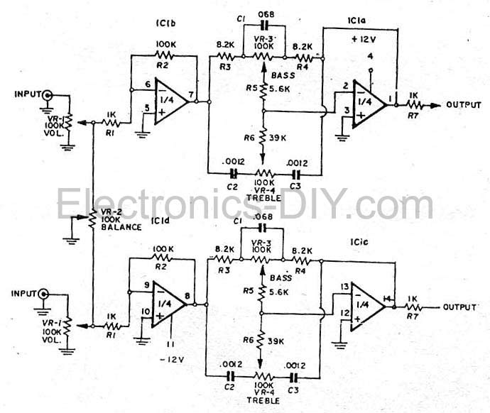
This simple tone control (bass and treble control) can be utilized in various audio applications. It can be integrated into amplifiers, function as a standalone control module, or even be incorporated into new and innovative instruments. The circuit employs...