
Horsepower Monitor
This torque measurement device operates by utilizing a sensor unit that is securely mounted to the automobile's drive shaft. The sensor detects the torque applied to the drive shaft during vehicle operation. The data collected by the sensor is transmitted wirelessly to a receiver unit using a 433 MHz RF data link, ensuring reliable communication over the required distance.
The sensor unit is equipped with a battery to allow for standalone operation, enhancing its flexibility and ease of installation. This battery-powered design also minimizes the need for complex wiring, reducing installation time and potential points of failure. The sensor processes the torque data and sends it as a digital signal to the receiver unit.
The receiver unit is designed to interface with a vehicle's data recording system or a portable computer through an RS-232 serial connection. This allows for seamless integration with existing automotive diagnostic tools or data logging software. Once the torque data is received, it can be combined with RPM measurements to compute the horsepower output of the vehicle, providing valuable insights into engine performance and efficiency.
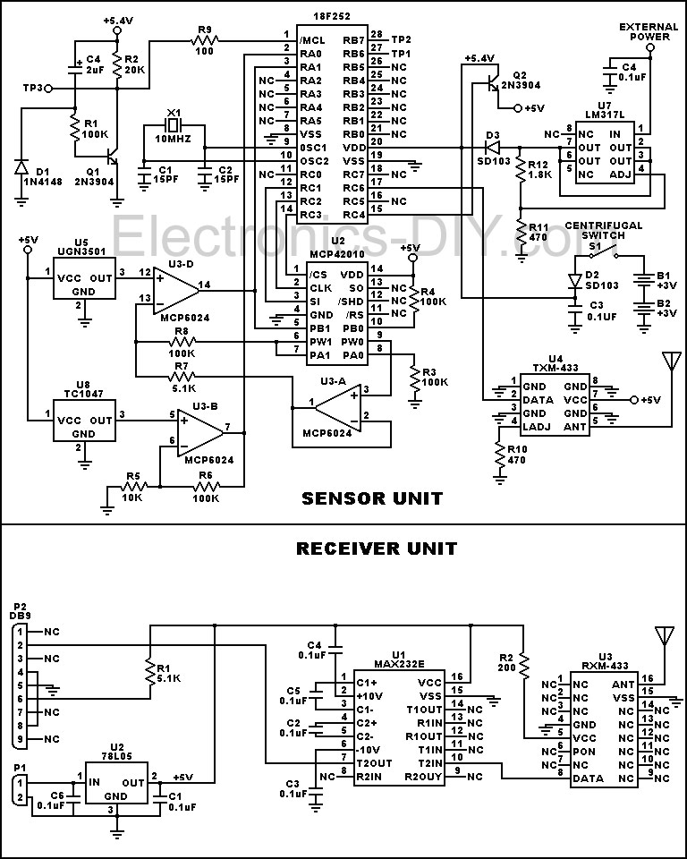
The circuit diagram illustrating the operation of this device includes essential components such as the torque sensor, RF transmitter, receiver, and the RS-232 interface. Each component is carefully selected to ensure accurate data transmission and minimal latency, which is crucial for real-time performance monitoring. The overall system design emphasizes reliability, ease of use, and compatibility with a wide range of automotive applications.This device is designed to measure the torque in an automobile drive shaft and provide an output to a vehicle data recording system or a portable computer via an RS-232 interface. The received data can then be combined with RPM measurements from the data recording system to calculate horsepower.
It consists of the sensor unit, (Figure 1), which attaches to the driveshaft, and the receiver unit, , which provides the serial output signal. The sensor unit is battery powered and communicates with the receiver via a 433 Mhz RF data link.The receiver unit is powered by the vehicle electrical system.
Circuit operation is shown in the diagram 🔗 External reference
Related Circuits
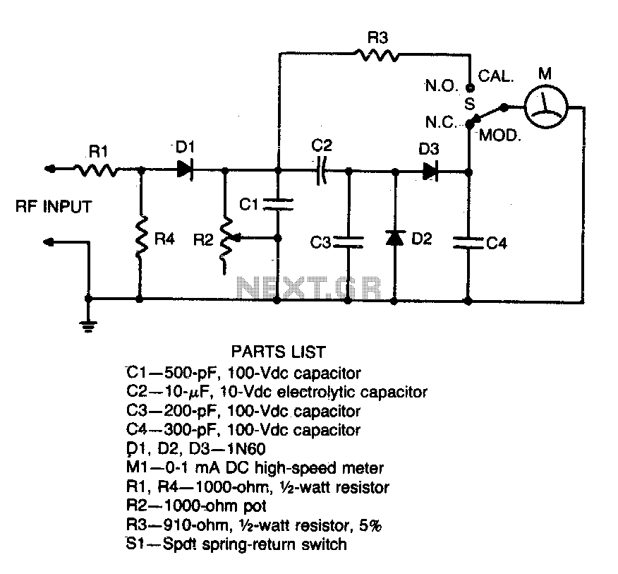
Connect this circuit to a transceiver using a coaxial T connector in the transmission line. Activate the transmitter (unmodulated), set switch 31 to CAL, and adjust resistor R2 for a full-scale reading. Return switch SI to the MOD position....
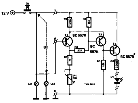
The circuit described below monitors the car's brake lights and indicates their operational status using a 12V light-emitting diode (LED). This functionality can prevent fines for driving with defective brake lights and enhance road safety. The monitor relies on...
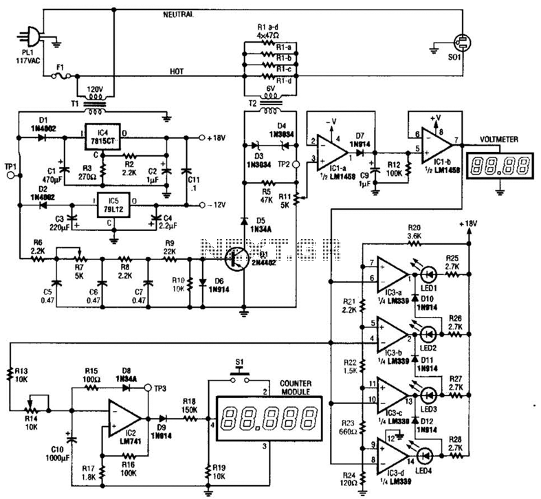
The ECM circuit comprises four sections, as illustrated in the block diagram. A power converter generates a voltage that correlates with the actual real power consumed by the load. This voltage supplies both a bar graph and a voltage-to-pulse...
this circuit uses the LM3914 and should be powered by its own battery, otherwise you might get an inaccurate reading. hook the to-be-monitored battery to pin 5 of the chip. More: all resistors are 5 or 10 percent tolerance,...
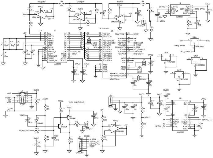
The circuit includes an ATmega88 as the main controller, an AD9280 ADC, an LM6134 high-speed quad op-amp, an LM1881 video sync separator, a 74HC4066 as a simple analog switch, and an RS-232 level converter. The LM1881 video sync separator...
This simple circuit allows for the monitoring of one's heartbeat, particularly useful during exercise. The transducer employed for pulse detection is an electronic component. This circuit typically incorporates a photoplethysmogram (PPG) sensor as the transducer to detect changes in blood...