
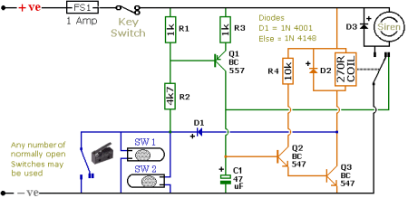
House Alarm Loop
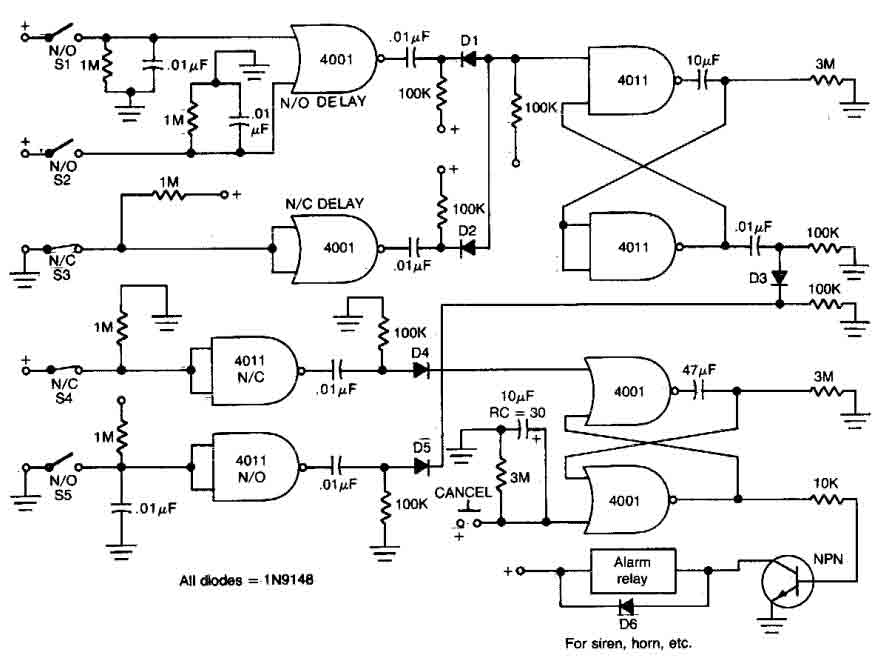
The alarm circuit is designed to provide a reliable security solution using a combination of open and closed loop switch contacts. The open loop contacts serve as sensors that detect unauthorized entry, while the closed loop contacts can be used for various applications, such as monitoring doors or windows. When any of the switches (1, 2, or 3) are triggered, the circuit activates the alarm system, ensuring immediate notification of a potential security breach.
The alarm remains active for a duration of 5 to 10 minutes, allowing sufficient time for an individual to respond to the alert. This time frame can be adjusted based on specific requirements or preferences. The inclusion of a 27-second triggering delay for both entrance and exit provides users with a grace period to deactivate the alarm before it becomes fully operational, thereby reducing false alarms during regular access.
To enhance user control, the circuit is equipped with a cancel button. This feature allows users to reset the alarm system back to its standby mode, ensuring that the system can be quickly reactivated without the need for a complete power cycle. The cancel button is strategically placed for easy access, promoting user-friendly operation.
Overall, this circuit design combines functionality with simplicity, making it suitable for various security applications where timely alerts and user control are paramount. Proper implementation of this circuit can significantly enhance security measures in residential or commercial settings.This circuit offers open and closed loop contacts (switches 1,2,3) that triggers the alarm ON and stays ON for 5 -10 minutes. The trigering delay (entrance/exit) is 27 seconds. This simple alarm circuit Has also a cancel button for reseting the circuit to stand-by mode again.. 🔗 External reference
Related Circuits
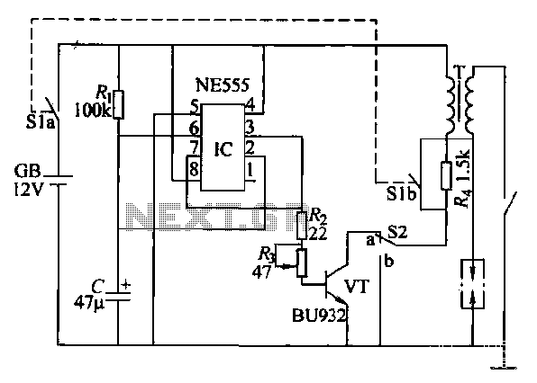
This paragraph describes an easy car alarm circuit that utilizes fewer components and is simple to produce. The circuit consists of an automobile anti-theft alarm system based on the NE555 timer, a power switch (VT), and a switch (S2),...
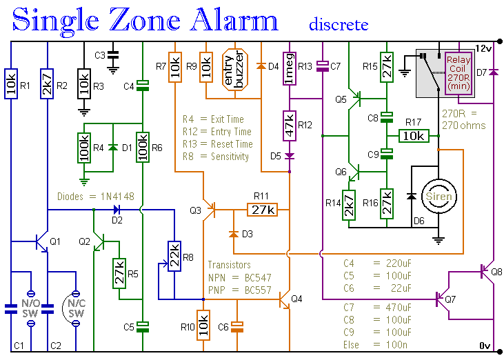
The circuit incorporates automatic exit and entry delays, a timed bell cut-off, and a system reset feature. It accommodates both normally-open and normally-closed switches and is compatible with standard input devices such as pressure mats, magnetic reed contacts, foil...
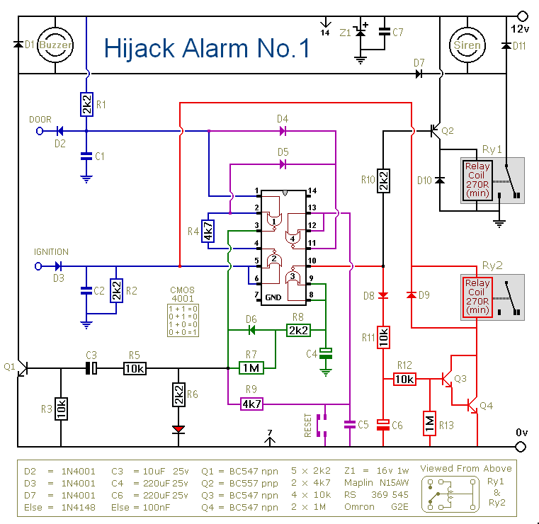
Before installing this or any other engine cut-off device in a vehicle, it is essential to carefully evaluate the safety implications of potential failures and the legal ramifications of implementing a device that could result in an accident. If...

This is a car alarm simulator that uses an LED as a simulation output. This simple circuit can indicate whether a car is running or not by detecting the voltage difference when the car is on and off. This...
The schematic illustrates a Simple Motorcycle Alarm Circuit Diagram created by Ron J. It incorporates micro-switches to safeguard removable panels and... The Simple Motorcycle Alarm Circuit Diagram is designed to enhance the security of motorcycles by utilizing a series of...
This circuit can be constructed using readily available low-cost components, some of which may be found in a junkbox. The specified value of 22 ohms for resistor R1 results in an average current of approximately 65 mA through the...
Warning: include(partials/cookie-banner.php): Failed to open stream: Permission denied in /var/www/html/nextgr/view-circuit.php on line 713
Warning: include(): Failed opening 'partials/cookie-banner.php' for inclusion (include_path='.:/usr/share/php') in /var/www/html/nextgr/view-circuit.php on line 713