
Taylor Source Follower
The circuit described utilizes a series configuration of octal tubes to create a visually appealing display while also exploring the functionality of tube-based and MOSFET-based amplifiers. In the case of the White cathode follower, the dual triode setup allows for efficient signal amplification with reduced distortion through its push-pull operation. The transition to a MOSFET-based configuration retains the core operational principles, offering a modern alternative with enhanced performance characteristics. The BUZ901 MOSFET, with its high power handling capabilities, serves as the primary active component, enabling the circuit to deliver substantial power output while managing thermal performance effectively. However, the design's limitations regarding power supply noise highlight the importance of careful circuit design and component selection to ensure optimal performance in real-world applications. Techniques such as using coupling transformers can be employed to mitigate noise issues, enhancing the overall fidelity of the amplification process. This comprehensive approach illustrates the intersection of vintage tube technology and modern solid-state components, catering to the preferences of audiophiles who appreciate both domains.I took 22 used, octal, 6. 3-volt, 600mA, controlled-warm-up tubes (mostly 6SN7s) and 22 octal tube sockets and an old extension cord and wired all the sockets in series. Then I plugged the series into a wall socket and reveled in the soft glow of 22 tubes (yes, I know only 20 were actually needed).
To add a bit more color, I dug out my biggest, most colorful film caps (about 40) and bent one lead over into a hook to hang from the tree ”plus any other shiny electronic part I could find. I am as often wrong as I am right. I expected to get many e-mails dealing with the Aikido amplifier, particularly its use in an SE amplifier; and I did.
But I also expected to get many e-mails dealing with the SS SRPP (the transistor-based SRPP amplifier). None were forthcoming. But a few wrote asking about the MOSFET-based White cathode follower (if only to find out where I had mentioned the topology before).
My guess is that transistors are just too creepy for most tube fanciers. (Interestingly, many of these same audiophiles are not bothered by our little silicon friends when they can`t see them, when they are imbedded in a DAC or OpAmp for example. ) Before looking at a MOSFET WCF, let`s do a quick review of the tube-based follower. Above, a classic White cathode follower is displayed. The top triode receives the input signal and it, in turn, drives the bottom triode. In other words, the WCF performs push-pull operation on the cheap, as it contains its own phase splitter.
What is the payoff, considering the added complexity Optimally, the circuit can deliver close to twice the idle current into its load, and with half the output impedance of a comparable cathode follower. Additionally, the distortion should be reduced because of the push-pull operation of a class-A output stage.
Class-A operation is a key feature, as the top triode can control the bottom triode only while it conducts; no conduction, no control. The same principle of operation applies to the MOSFET-based version of the classic circuit, excepting the the biasing arrangement, when enhancement MOSFETs are used.
The schematic above shows how easy the translation to silicon is to make. This circuit can be used as an unity-gain buffer, line stage, or power amplifier. As shown, the circuit defines a power amplifier capable of delivering about 36W into an 8-ohm load. The BUZ901 is an excellent lateral MOSFET that beats the pants off anything I have seen from International Rectifier. (If not available, then the Toshiba 2SK1530 is a good substitute. ) Although rated 125W, 1. 5A at 30 volts equals a lot of continuous heat dissipation for the BUZ901. Below is the BUZ901`s safe-operating-area graph. Note how close we come to the safe DC limit. Our nice looking, great-performing-in-SPICE power buffer suffers from one large problem, and it isn`t a high input capacitance.
The real world is populated with less-than-ideal power supplies, as power supply regulation is rare and expensive in a power amplifier. Unfortunately, this circuit cannot discern input signal from power supply noise. The problem lies with the sense resistor that develops the bottom MOSFET`s drive signal, as it attaches to the positive rail, not ground.
Thus, whatever noise is differentially present from the positive to negative power-supply rails will be seen as a signal to amplify. (A triode-based WCF with the similar bipolar power supply arrangement will suffer from the same failing.
) The solution is found in extracting only the audio signal ”not the noise ”across the sense resistor. One method would be to use a 1-to-1 coupling transformer, which wou 🔗 External reference
Related Circuits
This is a replacement power source for 1.3V mercury cells or other small batteries. It has many uses and I use this circuit in my computer to power a front panel multi adapter which has a digital thermometer. The described...
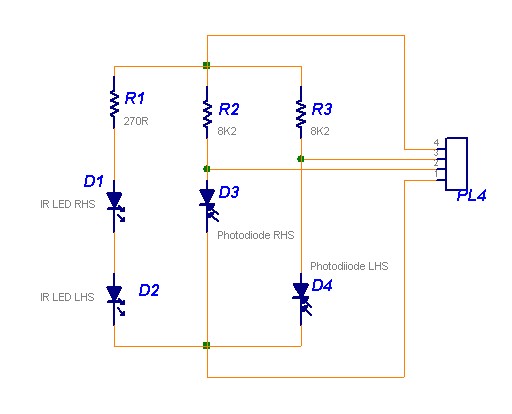
The following circuit illustrates a Line Follower Sensor Circuit Diagram. Features include a simple design, with Infrared LEDs D1 and D2 emitting infrared light. The Line Follower Sensor Circuit is designed to detect the presence of a line, typically a...
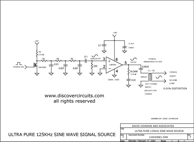
Ultra pure 125 kHz sine wave signal source. For certain RFID systems operating at 125 kHz, a very low distortion signal source is essential. The circuit presented here produces a 10-volt peak-to-peak signal. The ultra pure 125 kHz sine wave...
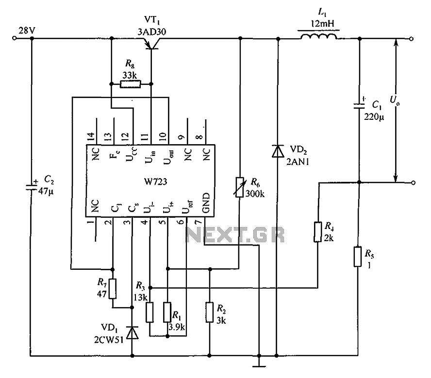
The Multiport W723 is an adjustable constant current regulator designed for use in switching regulator circuits, capable of delivering an output current of 1A. In the illustrated circuit, the W723 reference base voltage is approximately 7.2V. This voltage is...
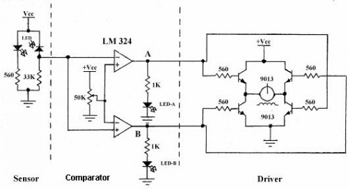
Line follower robots are commonly designed to follow a specific path on a track. Typically, these robots are controlled by microcontrollers; however, this article discusses a line follower robot designed without using a microcontroller. The assembly consists of three...
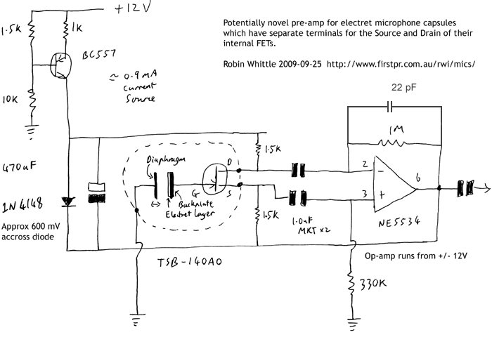
This circuit may be of interest to individuals designing preamplifiers for electret and externally polarized condenser microphones that lack an internal FET. If the noise from a single FET is a limiting factor, utilizing two or four FETs in...