
how to build a100 watt pure sine wave
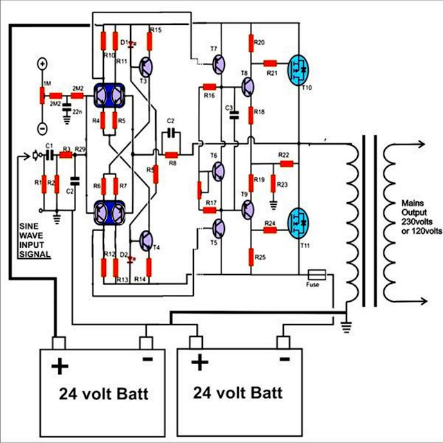
The described inverter circuit is designed for simplicity and effectiveness, emphasizing the use of a discrete differential amplifier formed by transistors T1 and T2. This configuration serves to amplify the low-level sine wave signal generated by the sine generator, ensuring that the output maintains high fidelity. The choice of transistors is critical; they must be selected based on their frequency response and thermal characteristics to optimize performance and minimize heat generation.
To address the common issue of overheating in sine wave inverters, this design incorporates techniques to reduce current draw. This approach not only prolongs the lifespan of the components but also enhances the overall efficiency of the inverter. By minimizing thermal stress on the output devices, the inverter can operate more reliably under various load conditions.
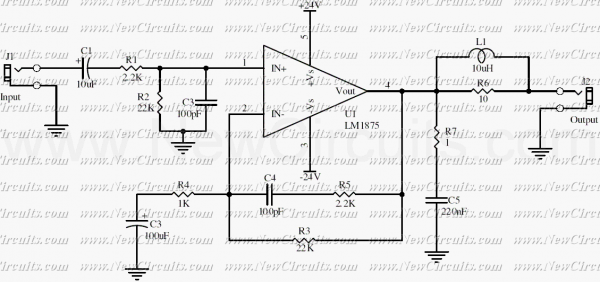
The output stage, which employs MOSFETs, is tailored to handle higher power levels while maintaining the integrity of the sine wave output. MOSFETs are preferred for their fast switching capabilities and lower on-resistance, which contribute to reducing power losses and improving thermal management. The design allows for scalability, enabling modifications to increase the output power beyond the base 150 watts, depending on the application requirements.
This inverter circuit is versatile and can be utilized to power a wide range of electrical devices, making it suitable for both residential and commercial applications. Its ability to produce a clean sine wave output ensures compatibility with sensitive electronic equipment, including computers, which require stable power sources to operate effectively. Overall, this circuit design represents a practical solution for achieving efficient power conversion while addressing common challenges associated with sine wave inverters.The circuit provided in this article shows you a simple way of building a useful liitle inverter thats easy to build and yet provides the features of a pure sine wave inverter. The circuit can be easily modified for getting higher outputs. The input stage consisting of T1 and T2 form a discrete differential amplifier, responsible for boosting the
low amplitude input signal from the sine generator. As we all know that the biggest drawback with sine wave inverters is its RED HOT output devices, which drastically reduces the over all efficiency of the system. This will help to reduce the current requirements of the circuit and thus help to keep the devices cooler.
The approach will also help to increase the efficiency of the system. Once this is done, you can rest assured of a clean, hassle free pure sine wave output that may be used for powering ANY electrical gadget, even your computer. Another power output stage is shown below using MOSFETs, which may be used in conjunction with the above discussed sine generator circuit for making a 150 watts high power pure sine wave inverter.
🔗 External reference
Related Circuits
Amplifier with IC number TDA7293 for processing sound systems. This amplifier includes inputs for a radio, TV, stereo, or other line-level devices. It also features a phono input for a record player, guitar, microphone, or other unamplified sources. With...
A UHF indicator, or wavemeter, is a device that measures frequencies and determines the resonance frequency of an LC circuit. This device operates without the need for radiation. The oscillator is constructed using transistors T1 and T2 (two BF494),...
The notch filter can be integrated into nearly any receiver to attenuate a specific frequency by over 30 dB. This filter is particularly useful for diminishing heterodynes and whistles. A notch filter, also known as a band-stop filter, is designed...
This circuit utilizes the versatile MAX038 function generator. While some advanced features of this IC are disabled in this configuration, it is capable of generating sine, triangle, and square waves by adjusting the A0 and A1 pins (refer to...
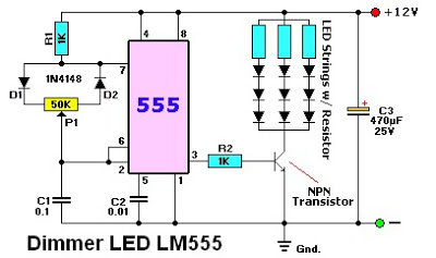
The LM555 timer IC can be utilized in various electronic projects, including the creation of an analog timer. According to the datasheet, the LM555 is versatile and can be adjusted to set timers based on specific requirements. The schematic...
This simple 20 watts audio power amplifier is designed for home-brewed purpose. The L1 should be able to handle a current up to 4A to drive speaker in full load. The distortion is 0.015% @ 1KHz / 20W. This...