
How to get power from RS-232 port
Many small circuits can effectively utilize the power available from the serial port, which is often overlooked. The design of these circuits must consider the limited current and voltage levels that can be drawn from the DTR and RTS lines. Careful attention to component selection, such as using low-power regulators and optimizing the load on the output lines, can enhance performance. Additionally, the design should ensure that the serial data transmission circuit remains efficient, utilizing discrete components that minimize power consumption while maintaining signal integrity.
For applications requiring additional power, integrating capacitors for energy storage may help stabilize the voltage levels during transient loads. Furthermore, implementing proper filtering and decoupling techniques will ensure that the power supply remains stable and free from noise, which is crucial for sensitive electronic components. The overall design should also consider thermal management, especially if the circuit is expected to operate continuously.
In summary, leveraging the power from a PC serial port involves strategic design choices, including component selection, circuit topology, and load management, to create functional and efficient electronic systems.This text tries to clear out the mystery of how to get power out of PC serial power. There are quite many small circuit which take all their operating power from serial port, where there are no real power output pin. Examples for this type of circuits are PC mouse and software protection dongle. You might wonder how this is possible. There is one way to get some power out of serial port: steal it from signal lines. When you are developing you own circuit which connects only the PC, then the only line which can be used are the output signal lines from PC serial port: DTS, RTS and TD. In normal operation situation DTR and RTS are raised so they give positive voltage output (about +12V when not loaded).
TD pin is in logic 1 when no data is sent which means that it is most time at negative voltage (-12V when not loaded) most of the time. The voltage at these outputs drop quite fast when load current is increase, because they are designed to drive normally only RS-232 input circuits (3-7 kohm resistance).
The voltage drops about 1-2 volts every every 1 mA of load current increase. Usually the short circuit current flow is 7-10 mA (this depends on the circuit types used in PC serial port). PC serial mouse uses typically DRT and RTS lines for generating +5V power for microcontroller circuit in the mouse.
Because typical optomechanical mouse also needs power for 4 leds in the optocoupler movement detectors, there is not much power to waste. Typical PC mouse might can have the following power requirements: "+15V 4mA -15V 4mA" (taken from Microsoft mouse bottom).
A typical approach make the power for microcontroller is to use diodes to take current from DTR and RTS lines and then feed it through resistor to all of the (infrared) leds in the movement detectors. All four (infrared) LEDs are connected in series, which gives about +5V voltage drop over all leds (typical to IR LEDs used in mouse).
This +5V is adequate power for low power mouse microcontroller. The serial data transmitting circuit consists of simple discrete transistor circuit to make it consume as little power as possible. The positive power supply usually taken from RTS and DRT lines (just after the diodes and before the resistor going to LEDs).
The negative supply for transmitter is taken from TD pin. Typical PC serial port mouse takes 10 mA total current and operates at voltage range of 6-15V. For more information about PC mouse operation check my PC mouse protocol document. Some schematics of working PC mouse impelementation can be found from PC Mouse Implementation Using COP800 (AN-681) from National Semiconductor and Implementing a Simple Serial Mouse Controller using PIC16C5x (AN519) from Microchip. The following circuit is an example how to get power from RS-232 serial port. It gives regulated +5V power for logic circuits and also unregulated positive and negative power supplies for RS-232 transmitting circuit.
The circuit gives only few milliampres power output because the power available from serial port is limited (and resistors R1, R2 and R3 limit current more). Modern PCs have typically 9 pin port instead of this older 25 pin port. If you want to use this circuit with such PC you have two options: use a 9 to 25 pin adapter or modify the circuit to 9 pin port.
To do the conversion you have to make the following modifications to the circuit pinout: You can get a little bit more current from the circuit if you leave out the resistors (R1, Rs, R3) and replace them with short piece of wire. 78L05 regulator takes 3-4 mA current all the time and needs at least 2V voltage drop, so if you can find a similar regulator which takes less current and has lower voltage drop, you get more current for your circuit.
One this kind of circuit can be found at. Some small circuits signal input circuit I have seen have taken positive and negative supplies for simple operational amplifier circuit just by using DTR and RTS 🔗 External reference
Related Circuits
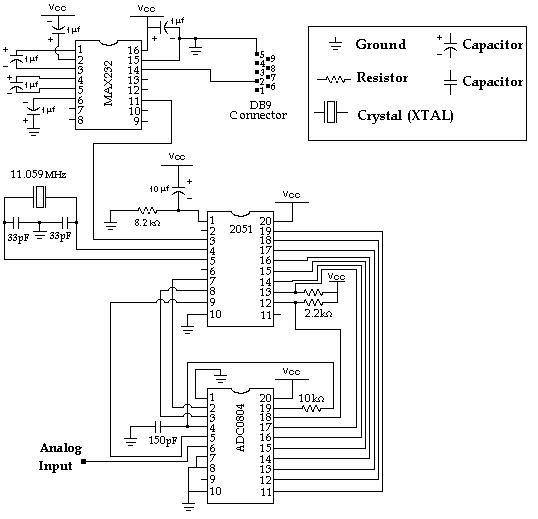
Data Collection - Analog to Digital Conversion and Communicating with a PC through the Serial Port Microcontroller Advanced Kit. The system described involves the process of data collection through analog-to-digital conversion, enabling communication with a personal computer via a serial...
Power pulse circuit using LM350 and NE555. This circuit can be used to drive lamps, power LEDs, DC motors, etc. Adjust R5 for output amplitude and R1 for output power. The LM350 is an adjustable 3-terminal voltage regulator. The power...
This application note outlines the design of a PC-based, 14-bit data acquisition system. It adopts a systematic approach, incorporating all essential components: analog, digital, hardware, and software. The document elaborates on each phase, emphasizing the testing of individual systems...
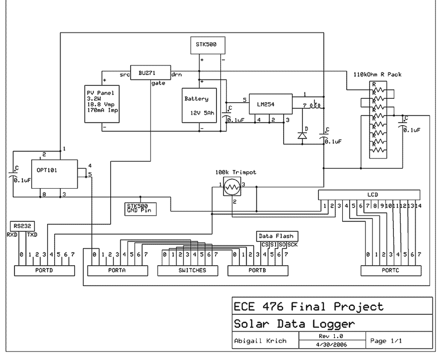
My project is a self-powered solar data logger. Put out in the sunlight, it will measure the light level and log this to memory to be later downloaded to a computer. The system is powered by a small solar...
The controller for a Hybrid Power Plant (HPP) block diagram consists of 440 Wp photovoltaic modules, a 1 kW wind turbine, and a 5 kW diesel engine as a backup. The HPP functions as a centralized PV and wind...
If you are looking at this page, you probably feel like I did when I tried to run a self-powered PIC programmer with my notebook computer. Yes, the serial port was the ultra-low-power type and wouldn't provide enough current...