
Self-Powered Solar Data Logger
More: The logger has a dedicated solar charging system to provide the needed power. A very simple charge controller regulates charging of a small, sealed gel-cell lead-acid battery by a small solar panel. This charge controller is a simple on-off switch that disconnects the PV panel when the battery voltage rises too high. The user sets the time and date each time the system is reset as well as the frequency with which data is stored. The user can also clear the memory or continue appending data to the previously logged data and extract logged data to a computer for analysis. The system is run by an interrupt-driven program to allow for accurate timing. An interrupt service routine decrements a series of task timers once per millisecond and the main task in the program calls various subroutines at predetermined intervals when their task timers run out and the appropriate flags are set to allow a task to run. Each of the eight buttons is polled separately once every thirty milliseconds. The only button that is not debounced is the LCD wake button as bouncing is not a concern with it. The debouncing routine is based on code written by Bruce Land and provided on the ECE 476 website. There is one task that prints to the LCD screen that is governed by a state machine indicating which set of messages is to be displayed and a variety of flags indicating which message within the sets is to be displayed. Having all LCD calls within a single task allows for the program to prevent any LCD communication while the LCD is off. If no buttons are pushed for two minutes, the system turns the LCD screen off to conserve power. The ADC is read once per second through a task called once per second that enables the ADC interrupt and starts a conversion. The ADC interrupt automatically switches between the two channels for the photodiode and the battery voltage, reading the battery voltage once for every five times the photodiode is read. To get an accurate battery voltage reading, the PV panel is disconnected just before the battery voltage reading is taken and then reconnected immediately after if the battery voltage is below 13V. If it is at 13 or above, the PV panel is not reconnected to prevent overcharging. If this system were to be commercialized, the most expensive piece of hardware is the photovoltaic panel. It would therefore be important to increase the efficiency of the system to utilize the PV panel as effectively as possible and reduce its size. This would be done in two ways. The first would be to have a maximum power point tracking charge controller rather than the simple on-off switch used in this project. This would keep the voltage of the solar cells at the maximum power point on the I-V curve and would effectively extract about thirty percent more power from the panel than allowing the battery to determine the voltage. The second way to improve efficiency would be to reduce the power consumption of the system. Because there was plenty of power from the PV panel and sufficient battery capacity, there was no need for this system to do more than turn the LCD screen off when idle. It would, however, be possible to reduce power needs further by reducing the clock speed of the chip, letting the chip go idle between readings or at night, and eliminating the LEDs on the STK500 board. The STK500 board was used in this project due to the integral flash memory and switches. Buying these components separately and building a custom board for the project would not have saved any money. However, if this system were commercialized, it is fairly obvious that the STK500 would not be used. It has many features that are unnecessary to this project and a much simpler board could be designed.
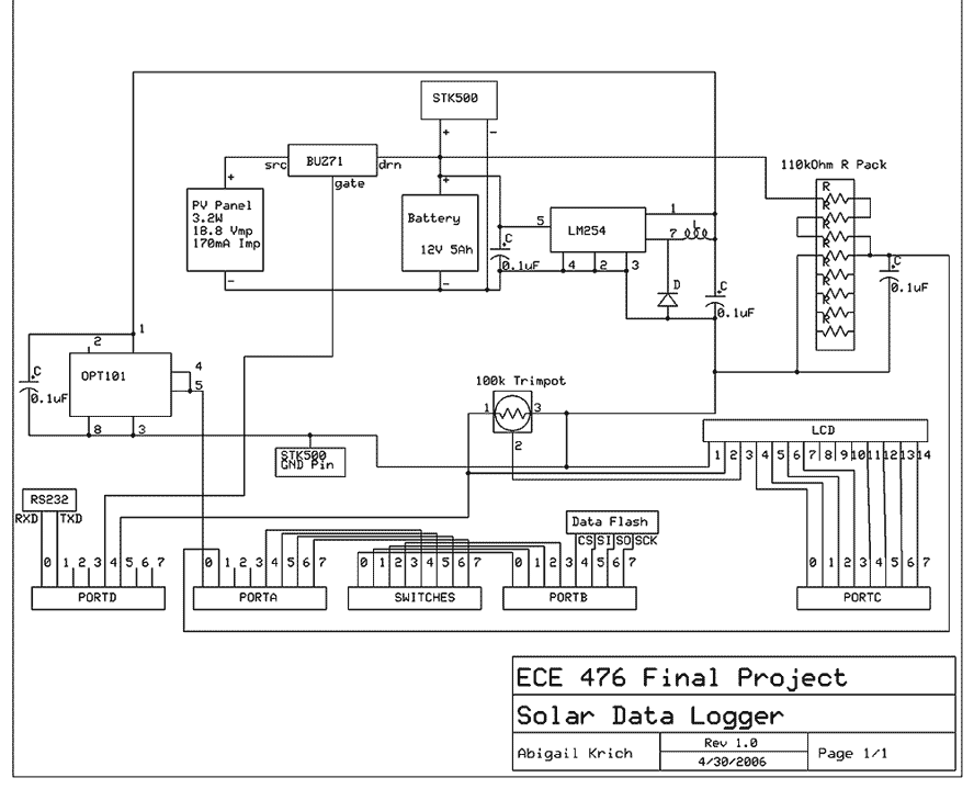
The self-powered solar data logger is an innovative design that employs a solar panel to harness energy for its operation. The core of the logger features a photodiode that serves as the primary sensor for measuring light levels. The analog output from the photodiode is converted into a digital signal using an Analog-to-Digital Converter (ADC), which is then stored in flash memory for future analysis. This operation is crucial for the system's functionality, allowing it to log data points along with their corresponding timestamps.
The system is powered by a small sealed gel-cell lead-acid battery, which is charged by the solar panel through a basic charge controller. This charge controller operates as an on-off switch that disconnects the solar panel when the battery voltage exceeds a predetermined threshold, preventing overcharging and ensuring battery longevity.
User interaction is facilitated through eight buttons, allowing the user to set the time and date, adjust the data logging frequency, and manage memory storage options. The system uses an interrupt-driven program to manage tasks efficiently. Each button is polled separately, with a specific routine implemented for debouncing, except for the LCD wake button, which does not require such handling due to its operational characteristics.
Data visualization is achieved through a small LCD screen that displays real-time information, including light levels, battery voltage, and logging duration. The LCD's power consumption is managed by turning it off after two minutes of inactivity, thus conserving energy.
The ADC is programmed to read the photodiode signal once per second, alternating between the photodiode and battery voltage readings. This is accomplished by disconnecting the solar panel during the battery voltage measurement to prevent inaccurate readings caused by the panel's output.
For potential commercialization, considerations for enhancing efficiency include implementing a maximum power point tracking (MPPT) charge controller and reducing overall system power consumption. These improvements would allow for better utilization of the photovoltaic panel and potentially decrease the size of the solar panel required for operation.
The STK500 board was selected for its integrated features, such as flash memory and switches, which streamlined the development process. However, a more simplified board design would be advisable for commercial applications to reduce costs and eliminate unnecessary features. My project is a self-powered solar data logger. Put out in the sunlight, it will measure the light level and log this to memory to be later downloaded to a computer. The system is powered by a small solar panel and battery. The solar logger I built uses a photodiode to measure the solar insolation level. It converts the analog signal from the photodiode to a digital value that is stored in flash memory. Every time the system logs a data point, it also logs the time and date so that the data can be analyzed in the future.
The logged data is available for a user to download to a computer for analysis. While the system is logging, real time data is displayed on a small LCD screen as well as information about the battery voltage, the length of time the system has been logging and the length of time it can continue to log before running out of memory. The logger has a dedicated solar charging system to provide the needed power. A very simple charge controller regulates charging of a small, sealed gel-cell lead-acid battery by a small solar panel. This charge controller is a simple on-off switch that disconnects the PV panel when the battery voltage rises too high.
The user sets the time and date each time the system is reset as well as the frequency with which data is stored. The user can also clear the memory or continue appending data to the previously logged data and extract logged data to a computer for analysis.
The system is run by an interrupt driven program to allow for accurate timing. An interrupt service routine decrements a series of task timers once per millisecond and the main task in the program calls various subroutines at predetermined intervals when their task timers run out and the appropriate flags are set to allow a task to run. Each of the eight buttons is polled separately once every thirty milliseconds. The only button that is not debounced is the LCD wake button as bouncing is not a concern with it. The debouncing routine is based on code written by Bruce Land and provided on the ECE 476 website. There is one task that prints to the LCD screen that is governed by a state machine indicating which set of messages is to be displayed and a variety of flags indicating which message within the sets is to be displayed.
Having all LCD calls within a single task allows for the program to prevent any LCD communication while the LCD is off. If no buttons are pushed for two minutes, the system turns the LCD screen off to conserve power. The ADC is read once per second through a task called once per second that enables the ADC interrupt and starts a conversion.
The ADC interrupt automatically switches between the two channels for the photodiode and the battery voltage, reading the battery voltage once for every five times the photodiode is read. To get an accurate battery voltage reading, the PV panel is disconnected just before the battery voltage reading is taken and then reconnected immediately after if the battery voltage is below 13V.
If it is at 13 or above, the PV panel is not reconnected to prevent overcharging. If this system were to be commercialized, the most expensive piece of hardware is the photovoltaic panel. It would therefore be important to increase the efficiency of the system to utilize the PV panel as effectively as possible and reduce its size.
This would be done in two ways. The first would be to have a maximum power point tracking charge controller rather than the simple on-off switch used in this project. This would keep the voltage of the solar cells at the maximum power point on the I-V curve and would effectively extract about thirty percent more power from the panel than allowing the battery to determine the voltage.
The second way to improve efficiency would be to reduce the power consumption of the system. Because I had plenty of power from my PV panel and sufficient battery capacity, there was no need for this system to do more than turn the LCD screen off when idle. It would however be possible to reduce power needs further by reducing the clock speed of the chip, letting the chip go idle between readings or at night, and eliminating the LED?s on the STK500 board.
The STK500 board was used in this project due to the integral flash memory and switches. Buying these components separately and building a custom board for the project would not have saved any money. However, if this system were commercialized, it is fairly obvious that the STK500 would not be used. It has many features that are unnecessary to this project and a much simpler board could be designed.
🔗 External reference
Related Circuits
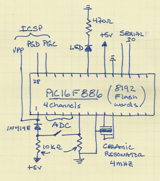
This project includes a few modifications from the Single Chip, Four Channel Datalogger article, so minimal detail will be provided. Below is the schematic. The changes from Dan's datalogger include the use of the PIC16F886, which is pin-compatible with...
The circuit below demonstrates how to construct a DAQ_LITE device, accompanied by an image of the finished PCB board. It is important to note that the 80mA fuse depicted in the image and the nearby protection diode are recommended...
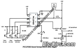
A data logger is a device that records measurements over time. The measurements could be any physical variable like temperature, pressure, voltage, humidity, etc. This project describes how to build a mini logger that records surrounding temperature. A data logger...
A voltage regulator is connected across the solar cell to prevent damage to the storage battery due to overcharging. A series diode prevents the array from discharging the battery during hours of darkness. The regulator does not draw power...
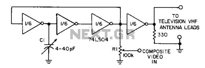
Three gates of a 74LS04 form the oscillator circuit. Capacitor C1 allows fine frequency adjustment to a specific television channel and helps stabilize the circuit. Potentiometer R1 acts as the mixing input and provides adjustment of the contrast ratio...
The input signal is processed with an electronic low-pass filter to eliminate all frequencies above the Nyquist frequency, which is half of the sampling rate. This process is essential to prevent aliasing during sampling and is referred to as...