
How to Make a Simple Metal Detector Circuit Using IC CS209A
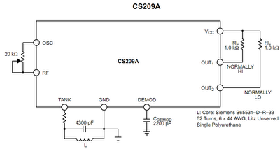
The metal detector circuit utilizes an LC resonant tank circuit, comprising an inductor and capacitor, to establish a specific resonant frequency. The IC CS209 acts as the core of the oscillator, generating a signal that is influenced by the surrounding environment, particularly by the presence of metallic objects. The resonance condition is critical; when the frequency of the oscillator aligns with the natural frequency of the LC tank circuit, the impedance peaks, allowing for optimal energy transfer.
As a metal object approaches the inductor, it alters the inductance, which in turn modifies the Q factor of the LC circuit. This change results in a reduction of the voltage amplitude across the LC network. The oscillator's feedback mechanism responds to this drop in amplitude, causing the output states to switch when a predetermined threshold is reached. This design ensures that the circuit can detect even small changes in inductance due to nearby metallic objects.
The capacitor connected to the demodulator plays a crucial role in signal processing. When a metallic object is detected, the internal current source charges the capacitor, allowing for the detection of the presence of metal. The diversion of current during detection creates a negative feedback loop that stabilizes the circuit, enhancing its reliability. The hysteresis effect introduced by the reference voltage of approximately 1.2 volts prevents spurious signals from causing false positives, thus improving the overall performance of the metal detector.
In summary, this metal detector circuit demonstrates a practical application of LC resonance principles, utilizing feedback mechanisms within the IC CS209 to achieve sensitivity and accuracy in detecting metallic objects at varying distances.The principle of operation of the proposed metal detector circuit is quite basic yet very interesting. The detecting function is triggered by sensing the decrease in the Q level of the LC network associated with the circuit in the presence of a metal at a specified proximity level.
Basically the built-in oscillator of the IC CS209 is made function al with the inclusion of a parallel resonant LC tuned network in conjunction with a feedback resistor wired up with the OSC and RF pin outs. The impedance of the tuned resonant network may be expected at the maximum level as long as the driving source frequency is equal to the resonant frequency of the LC circuit network.
On detecting the presence of a metallic object at a close proximity to the inductor sensor, the voltage amplitude of the LC network gradually begins to fall corresponding to the closeness of the metal to the inductor. Due to the above factor when the oscillation frame of the chip drops and reaches a certain threshold level, triggers the position of the complementary outputs such that they change states.
Referring to the figure, as soon as a metal object is detected at the inductor input, the capacitor connected to the DEMOD gets charged through an in built current source of 30 uA. However during the detection process the above current gets deviated away from the capacitor proportionately with the generated negative bias on the LC network.
This resulting reference level then equals near about 1. 2 volts which introduces some sort hysteresis in the circuit, and becomes ideally suited for preventing wrong or false triggering. Position a metal object at relatively larger distance away from the inductor, assuming the Q of the LC to be at the maximum sensitivity and the distance to be within the allowable range provided by the Q factor of the inductor.
🔗 External reference
Related Circuits
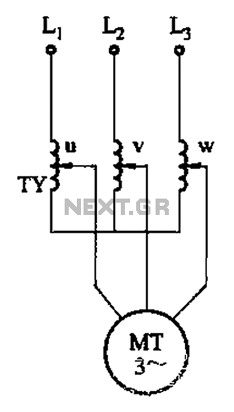
The circuit depicted in Figure 3-176 illustrates an adjustment method that allows the motor to operate at equilibrium. The adjustment range is relatively wide; however, it necessitates a three-phase voltage regulator, which incurs higher input costs. The circuit design in...
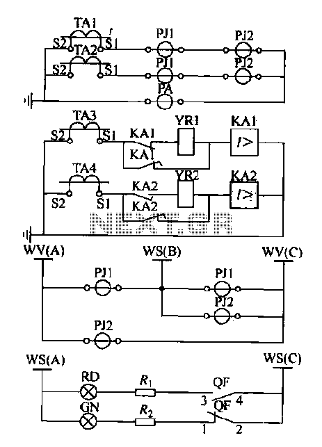
Expanding schematic circuit for the secondary circuit of high-voltage lines. The schematic circuit for the secondary circuit of high-voltage lines is designed to enhance the distribution and management of electrical power in high-voltage systems. This circuit typically includes components...

This circuit was utilized with an audio power amplifier to identify the point at which the output is -3 dB from maximum, indicated by LED D5, and at clipping, shown by LED D6. The indicator can be employed with...
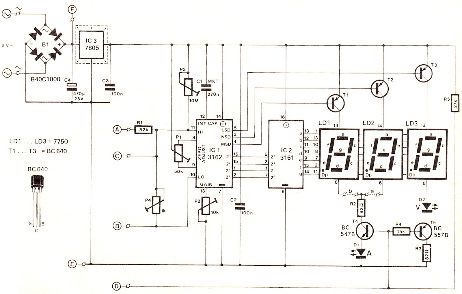
This voltage/current (V/I) display module is well-suited for integration into an existing DC power supply, providing precise readings of the set voltage or the current consumption of the load. The voltage measurement range features a decimal point indicator (LD3),...
It is recommended to have a fuse in the power line and to always have a load connected while power is being applied. The fuse should be rated at 10 amps per 100 watts of output. The power leads...
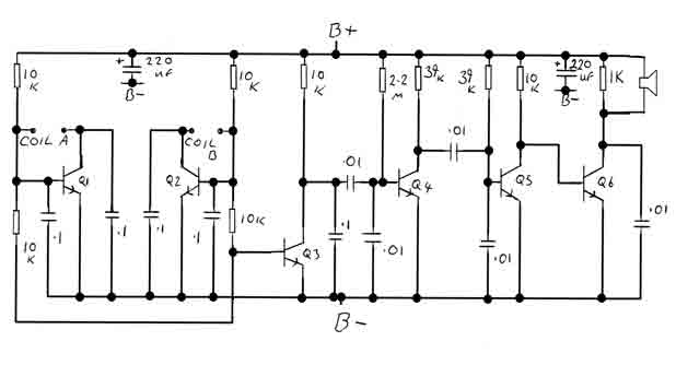
By adjusting the oscillators so their frequencies are very nearly the same, the difference between them is made audible as a beat note. This beat note changes slightly when the search loop is moved over or near to a...