
100w inverter circuit by irf44 mosfet
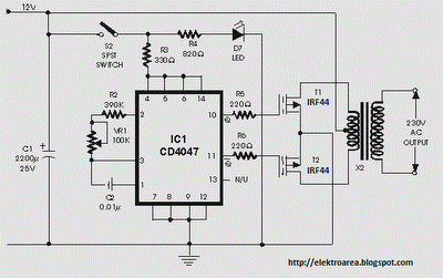
In electronic circuits, the inclusion of a fuse in the power line serves as a critical safety mechanism to protect against overcurrent conditions that could lead to component damage or fire hazards. The specification of a 10-amp fuse per 100 watts of output is based on the principle of ensuring that the fuse can handle the maximum expected current without blowing under normal operational conditions. For instance, in a 100-watt load scenario, the current draw would be approximately 1 amp (100 watts / 100 volts = 1 amp), which is well within the limits of the specified fuse rating.
Moreover, the requirement for a load to be connected while the power is applied is essential to prevent potential damage to the power supply or circuit components. Without a load, the power supply may experience excessive voltage levels, leading to instability or failure.
The choice of wire gauge for the power leads is equally important. The wire must be capable of handling the high current draw without overheating. Using the American Wire Gauge (AWG) standard, for a current draw of 10 amps, a minimum wire gauge of 18 AWG is typically recommended for short runs. However, for longer distances or higher ambient temperatures, a heavier gauge, such as 16 AWG or even 14 AWG, may be necessary to ensure safe operation.
In summary, the design considerations for integrating a fuse and ensuring proper load connection and wire gauge are fundamental to creating a reliable and safe electronic circuit. These elements work together to mitigate risks associated with electrical faults and ensure the longevity and performance of the system.It is recommended to Have a Fuse in the Power Line and to always have a Load connected , while power is being applied. The Fuse should be10 Amps per 100 watts of output. The Power leads must be heavy enough wire to handle this High Current Draw. 🔗 External reference
Related Circuits

When an alarm or notification is needed after ten minutes, the circuit illustrated below can be utilized. This circuit is essentially a monostable multivibrator based on the IC NE555. When the reset push button is pressed, the green LED...
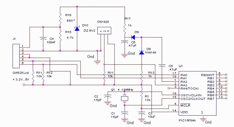
The DS18S20 digital thermometer offers a precision of 0.5 °C, with the SCRATCHPAD being read every 800 ms. Capacitors C5 and C6, along with diodes D8 and D9, form a voltage doubler to power the LCD panel. The DS18S20...

A circuit diagram of the T1 is a low-impedance output transformer, featuring a 5000-8 ohm resistor. The T1 low-impedance output transformer is designed to match the output of audio amplifiers to the impedance of loudspeakers, ensuring optimal power transfer and...
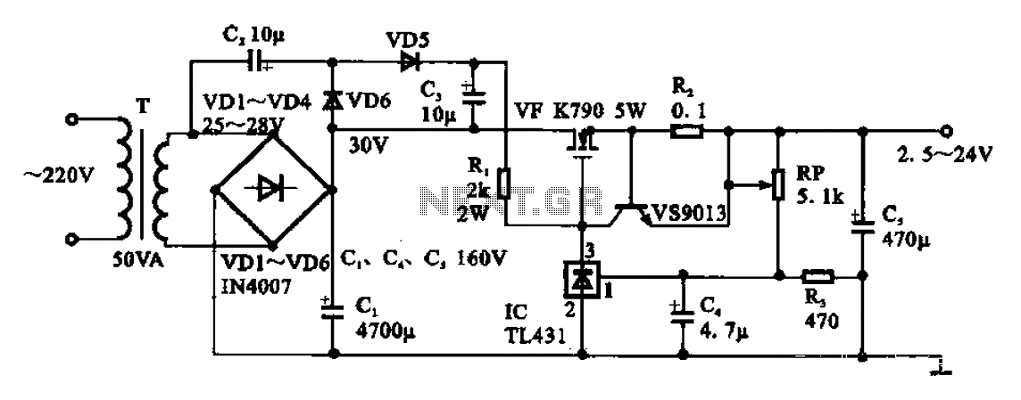
An adjustable DC power supply circuit is presented, consisting of a step-down transformer (T), a rectifier bridge (VD1 to VD4), and additional components. The voltage regulator circuit includes an adjustment potentiometer (RP, 5.1 kΩ), allowing the output voltage to...
Even though the power was off, there was AC present at the handle plug, and a short circuit occurred. Upon disassembly, a blown transistor was discovered. An attempt was made to fix the issue, but after one month and...

R1 and R2 are carbon composition resistors labeled as Va or Vi. K1 is a 12 V DPDT DIP relay. Illustration A demonstrates the connection of the relay contacts for use with a separate transmitter-receiver combination. The circuit is...