
How to make a solar powered robot
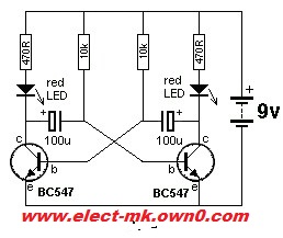
The circuit utilizes a CMOS 1381 voltage-controlled trigger, which is a versatile component capable of operating at various voltage limits. In this application, it is essential to ensure that the selected 1381 part is compatible with the motor voltage, specifically 2V. The motor is connected to the capacitor, which serves as a temporary energy storage device, allowing the robot to perform movements powered by solar energy collected from the solar panels.
The capacitor value of 3300µF can be modified based on the desired performance characteristics of the robot. A higher capacitance value, such as 4700µF indicated in the diagram, will lead to longer operational bursts but will also extend the idle intervals between movements. This trade-off allows for fine-tuning the robot's behavior to match specific requirements or preferences.
The circuit can function without a diode, which is typically used to prevent reverse current flow from the battery to the solar panel. In this design, since there is no battery involved, the diode is not necessary. However, if a diode is incorporated, any standard diode can be utilized, as the specific ratings are not critical for this application.
To optimize the robot's performance, varying the resistor values in conjunction with the capacitor adjustments is recommended. This will influence both the intensity of the motor's operation and the timing of the movements, allowing for a customizable robotic behavior. When the solar panel generates sufficient energy to charge the capacitor to a predetermined threshold, the 1381 component activates the motor, enabling the robot to perform its programmed actions.
In summary, this circuit design provides a practical and educational platform for developing electronic skills while experimenting with solar energy and robotic movements. The simplicity of the connections, combined with the ability to modify component values, offers a valuable learning experience for those interested in electronics and robotics.One 1381 part (CMOS voltage-controlled trigger available at different limits) Get one that matches the voltage across your motor (2V in this case) 8. The other terminal of the motor is connected to the 3300uf capacitor which is in turn connected to the other terminal of the solar panels.
(The diagram shows 4700uf. Don`t worry. As you will see later, the values can be altered to get different effects for the robot. ) Ans: This project will help you develop the confidence on many future electronic projects. Do not worry if you don`t get it right the first time. The connections are simple but they may get confusing for the first timer. So make atleast two or three attempts before giving up. If you make those attempts, you surely will not have to give up is our belief. Ans: The diode can actually be discarded. The diode is actually added to prevent the battery discharge through the solar panel. Since we are not using a battery and the circuit does not need the capacitor to retain charge when the panel is not in the light, the diode becomes superfluous. But as we said, this is based on the Miller solar engine and so the circuit diagram shows the diode. If you are using one, any diode will do. The specifications are not important. 2. Vary the resistor and capacitors to find the optimum solution for your robot. This will alter the power going to the motor ( and hence the intensity of the robot movements) and the time interval between the movements.
The solar energy is stored by charging the capacitor in circuit and when a threshold level is reached, the 1381 part gets triggered and works the motor. 4. The values of the small capacitor determine the burst` of activities. Larger the values, longer will be the dance but intervals between will also be longer and vice versa.
🔗 External reference
Related Circuits
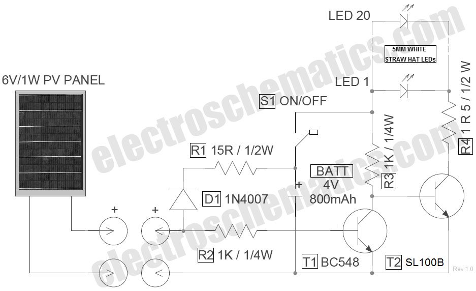
The circuit for the LED solar lantern lights is designed using a 6V/1W solar panel (photovoltaic panel) and a 4V/800mAh lead-acid battery. The schematic for the LED solar lantern circuit incorporates a solar panel that converts sunlight into electrical energy....
For a robot to perform its assigned tasks, a controller is necessary. This controller may be mechanical, electrical, electronic, or a combination of these. It acts as the brain of the entire system, providing the robot with its intelligence....
The strategy focused on efficiently navigating complex terrain with superior speed. The objective was to score in the lowest scoring goal by acting quickly to limit the opposing team's points. The mechanical and electrical designs prioritized speed, resulting in...
Iron the printed layout at a low heat setting until the ink adheres to the PCB. This process may take over an hour to complete. Afterward, remove the transparent paper. Next, submerge the PCB in Ferric Chloride solution until...
Robot eyes circuit of Service. A simple circuit to simulate a man appointed to it. It consists of a dual-lamp working in an unsteady manner. Circuit diagram. The robot eyes circuit is designed to create a visual effect that simulates...
This circuit is a modified version of a function-generator circuit. It features a battery-powered sine wave generator that can be continuously adjusted from 100 Hz to 10 kHz. The described circuit utilizes a sine wave generator to produce a continuous...
Warning: include(partials/cookie-banner.php): Failed to open stream: Permission denied in /var/www/html/nextgr/view-circuit.php on line 713
Warning: include(): Failed opening 'partials/cookie-banner.php' for inclusion (include_path='.:/usr/share/php') in /var/www/html/nextgr/view-circuit.php on line 713