
Mains surge suppression
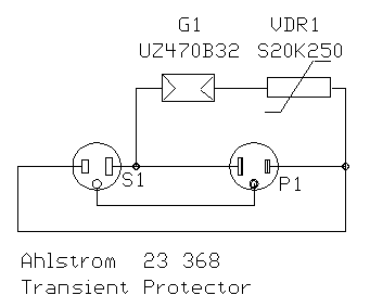
The surge suppressor circuit is engineered to mitigate the risk of damage to electronic devices from voltage spikes that may occur in electrical systems. The primary components include a voltage-dependent resistor (VDR), which exhibits a decrease in resistance when exposed to high voltage levels, effectively clamping the voltage to a safe level. Additionally, the gas surge suppressor provides an alternative path for excess current during transient events, further enhancing protection for connected devices.
The design's capability to operate within a maximum voltage of 230V AC and a current of 16A ensures compatibility with standard household and commercial electrical systems in Finland. The integration of both a VDR and a gas surge suppressor allows for effective suppression of both high-frequency noise and transient surges, making the circuit versatile for various applications.
The circuit's configuration allows for easy installation between the mains outlet and the protected equipment, ensuring that all devices connected downstream are shielded from potential overvoltage conditions. The absence of common mode surge protection indicates that this device is primarily focused on differential mode transients, which are more common in typical electrical disturbances.
Overall, the "Ahstrom Transienttisuoja 23 386" surge suppressor circuit serves as a reliable solution for safeguarding sensitive electronics, particularly in environments where voltage transients are a concern. Its robust design and straightforward functionality make it an essential component for protecting valuable electronic equipment.The following circuit is a schematic of mains surge suppressor circuit manufactured by StrG¶mfors and sold undel model name "Ahstrom Transienttisuoja 23 386". It is designed for protecting sensitive electronic devices agains overvoltage transients in normal mains voltage.
The circuit is designed for use in Finland where the mains voltage is 230V A C and the maximum fuse size for mains connector group is 16A. The surge protector is connected between main outlet and the equipment to be protected. The protector handles G³nly the overvoltage between live and neutral wires (no common mode surge protection). This surge protector is suitable to be used with both grounded and non-grounded wall outlets. Operation voltage 230 V AC Max. Operation current 16 A Max. group fuse size 16 A Cutting voltage (0, 2/50 microsecond pulse) 850 V @ 80 A Max. current pulse (8/20 microsecond pulse, 10 pulses) 2000 A The circuit is quite basic surge suppression circuit which consists of VRD and gas surge suppressor connected in series.
The protection circuit is connected between live and mains leads. 🔗 External reference
Related Circuits
This is a simple frequency counter designed to monitor the 240VAC mains supply. It has a frequency range of 0-999Hz, allowing it to also be used with 400Hz equipment. The frequency counter circuit operates by measuring the frequency of an...
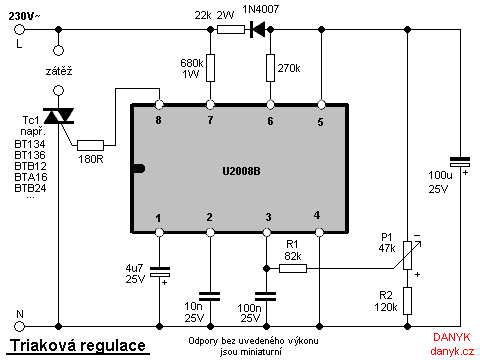
Triac regulation is designed to control the power of mains appliances. It can adjust the brightness of incandescent light bulbs, halogen lamps, dimmable energy savers, heaters, and other thermal devices, as well as regulate motors. The power can be...
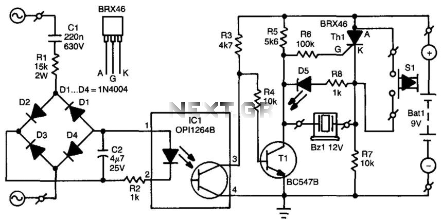
When the mains voltage is present at the input terminals, the transistor in the optocoupler is activated, T1 is off, and the silicon-controlled rectifier (SCR) Th1 is in the conducting state. As a result, both terminals of the piezoelectric...

As the only electronics engineer in the family and circle of friends, it is sometimes challenging to decline requests for assistance. Recently, a friendly elderly lady in a retirement home sought help regarding her lighting situation. In her room,...
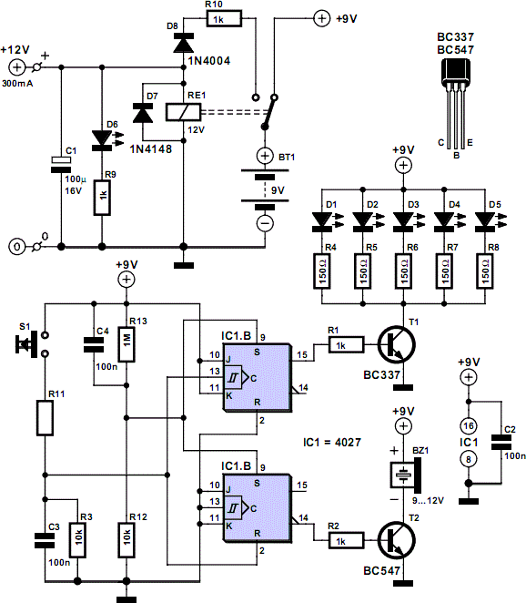
When the push button is pressed, a clock pulse appears on the CLK input of flip-flop IC1b. The output then toggles, causing the LEDs to turn off. Simultaneously, IC1a is reset, silencing the buzzer. Pressing the button again will...
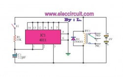
The function of this circuit is to prevent equipment damage caused by pressure and to provide a delay for other appliances connected to the output of the relay. The circuit includes components such as a 4011 IC, a diode,...
Warning: include(partials/cookie-banner.php): Failed to open stream: Permission denied in /var/www/html/nextgr/view-circuit.php on line 713
Warning: include(): Failed opening 'partials/cookie-banner.php' for inclusion (include_path='.:/usr/share/php') in /var/www/html/nextgr/view-circuit.php on line 713