
hv dc dc converter
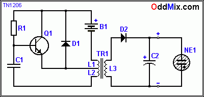
Table 1. Input and Output Voltage for HV Oscillator:
- Input Voltage: 6 V, Current: 80 mA; Output Voltage: 400 V, Load Voltage: 165 V
- Input Voltage: 9 V, Current: 120 mA; Output Voltage: 600 V, Load Voltage: 165 V
The NPN transistor Q1 operates in a saturated mode as a switch, functioning safely and coolly even while switching significant power. The D1 diode is crucial for protecting the transistor from high voltage inductive kicks. The output power can increase with a larger ferrite core, particularly with a toroid, and a slower operating frequency. The C2 filter capacitor eliminates most of the ripple. A voltage regulator can also be added if necessary, which can be as simple as a neon bulb with a series pass transistor.
Parts list for High Voltage DC to DC Converter:
- B1: Battery, 5 - 9 Volt
- C1: Capacitor 180 pF - 0.01 uF, 200 VDC, Mica or Disc
- C2: Capacitor, 0.1 uF, 200 VDC, Disc or Film
- D1, D2: Diode 1N914
- NE1: Neon Bulb, 165 VDC
- Q1: Transistor, 2N2102, NPN, HS Switch
- R1: Resistor 2 K, 5%, 1/4W, CC
- TR1: Transformer L1=15T - L2=5T - L3=400 Turns on Ferrite
The described circuit provides a practical solution for generating high voltage from low voltage sources, utilizing readily available materials and components, while maintaining efficiency and reliability in operation. The careful selection of ferrite materials and winding techniques contributes to the overall performance of the oscillator circuit. By adhering to the specified parameters and ensuring proper assembly, this circuit can be effectively employed in various high voltage applications.Occasionally high voltage is necessary for experimenting with traditional vacuum tubes, cold cathode displays or other circuits that require high voltage (B+) power supplies. There is a way to avoid high voltage for tube circuits by using space charge tubes but those tubes are difficult to find.
Oscillator circuits can be used to provide high voltage with modest power as a simple DC to DC converter. This HV [High Voltage] oscillator circuit uses a single round ferrite piece for a transformer core. The diameter of this ferrite core is 8 [MM], and it is 19 [MM] long, but these dimensions are NOT critical. Almost any ferrite piece will do nicely. Standard transformer laminations are not very useable for this project because of their heavy iron magnetizing losses due to the high oscillator frequency.
If a long ferrite antenna rod is available - from an old radio - a small piece can be broken off to serve the purpose. Even an old threaded ferrite tuning screw from an RF coil will be fine, or a small size toroid coil - if it is ferrite and not powdered iron - will be even better.
It is onto this ferrite core the L3 coil is wound first. L3 is 400 turns using 0. 1-0. 2 [MM] enameled, solid copper wire. Almost any size wire is useable but it has to fit onto the core. Nothing fancy required with this winding, it is just done by free hand. Once this high voltage coil is made the rest of the HV transformer is easy. Using heavier gage enameled wire, or even regular general purpose hook-up wire, whatever is available, L1 - 15 Turns and L2 - 5 Turns coils are made. The wire gage and the number of turns can be varied around bit. With more turns the secondary voltage available will decrease - along with the frequency - in accordance with the turn ratio.
Winding less turns is not advised as the present frequency of the oscillation is already in the Megahertz range and this high frequency results in more magnetizing losses. The dimension of the Vector board is 70 x 50 [MM] or 7 x 5 [cm] - about 3 x 5 [inches], also not critical.
Any size vector board can be used. The oscillator design uses many common, readily available parts and it is easy to build or change as required. The output of this converter is in the 400 - 600 volt range - see Table 1 - depending on the type of the output transformer and the load.
Loaded with a NE1 Neon Bulb, it is a stabilized at 165 VDC. Table 1. Input Output Voltage for HV Oscillator: - Input Input Output Output Voltage Current Voltage Load Voltage Current No Load NE1 - 6 V 80 mA 400 V 165 V 9 V 120 mA 600 V 165 V - Because the NPN transistor Q1 operates in a saturated mode as a switch that operates safe and cool even while switches significant power. D1 diode is important to protect the transistor form the high voltage inductive kicks. The output power can be more with a larger ferrite core - especially with a toroid - and a slower operating frequency.
The C2 filter capacitor removes most of the ripple. A voltage regulator can also be added if needed. It can be as simple as a neon bulb with a serious pass transistor. Parts list for High Voltage DC to DC Converter: B1 - Battery, 5 - 9 Volt C1 - Capacitor 180 pF - 0. 01 uF, 200 VDC, Mica or Disc C2 - Capacitor, 0. 1 uF, 200 VDC, Disc or Film D1, D2 - Diode 1N914 NE1 - Neon Bulb, 165 VDC Q1 - Transistor, 2N2102, NPN, HS Switch R1 - Resistor 2 K, 5%, 1/4W, CC TR1 - Transformer L1=15T - L2=5T - L3=400 Turns on Ferrite 🔗 External reference
Related Circuits

The 24V to 12V converter schematic is straightforward; however, it is important to ensure that all components, including transistors and integrated circuits, are adequately heat dissipated and electrically insulated from metal surfaces. The schematic diagram is derived from the...

This power converter is utilized in the LHC machine to supply power to superconducting magnets. It is situated within the underground installation of the LHC, positioned close to the loads to minimize cable losses. The converter operates at a...
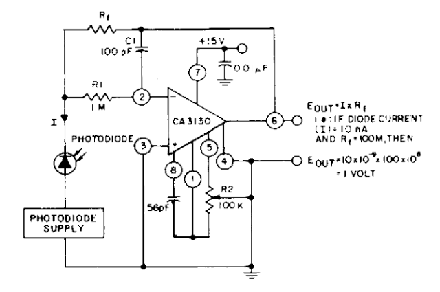
The photodiode current-to-voltage converter circuit employs three CA3130 BiMOS operational amplifiers, designed for applications that require sensitivity to sub-picoampere input currents. This circuit generates a ground-referenced output voltage that is directly proportional to the input current flowing through the...
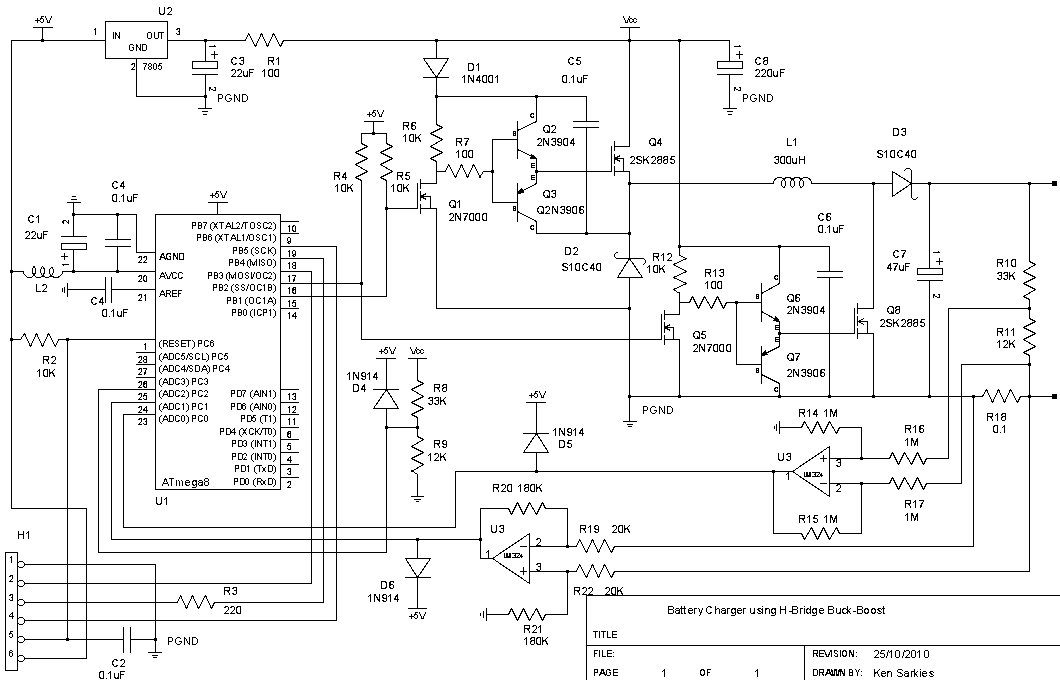
The buck-boost converter is valuable when the output and/or input voltages fluctuate significantly, necessitating the use of a buck converter at times and a boost converter at others. An example, which will be elaborated on in a future project,...
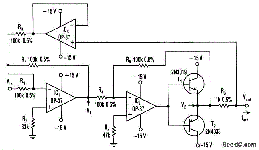
This voltage-to-current converter utilizes three operational amplifiers to control a pair of power transistors. The output current is determined by the formula: IOUT = Vin/R6. The output resistance exceeds 50 MΩ, and the output current can vary from 1...
This circuit utilizes the CA3306, a family of CMOS parallel (flash) analog-to-digital converters designed for low power and high-speed applications. The CA3306CE operates at sampling rates of up to 10 million samples per second, while the CA3306E can achieve...