
Icom IC-751 (IC 751 IC751) transceiver mods reviews software and diagrams
 transceiver mods reviews software and diagrams")
The circuit design of the 751 audio system incorporates several critical components and configurations that affect its performance and functionality. The audio path begins after the detector stage, where the audio signal is processed through a series of electrolytic capacitors, which serve to block DC components while allowing AC audio signals to pass. These capacitors are crucial in maintaining the integrity of the audio signal by preventing unwanted DC offset from interfering with the audio processing.
The electronic switches (IC7 C and D) play a pivotal role in muting the audio during transmission and managing the monitor/sidetone circuit. Their operation is essential for ensuring that the audio path is correctly configured depending on the mode of operation—receive or transmit. However, their inherent switching characteristics can introduce unwanted transients into the audio path, particularly when switching states. The observed thumping noise was likely caused by these transients, which were exacerbated by the high gain of the audio amplifier.
The audio amplifier itself is designed to operate at full gain continuously, with the volume control implemented through attenuation in IC 6A. This design choice leads to very low audio signal levels in the earlier stages of the circuit, making it challenging to diagnose issues with standard measurement tools. The addition of a dedicated amplifier for the oscilloscope allowed for better visibility of these low-level signals and facilitated the identification of the actual problem—charging and discharging behavior of the DC blocking capacitors in the audio path.
The modifications made to bypass the electronic switches and connect the audio and monitor stages directly to the audio amplifier provided a temporary solution to the thumping issue but also highlighted the need for careful consideration of the circuit's design and functionality. The discovery that the electronic switches were not necessary for CW operation further emphasizes the importance of understanding the specific requirements of the audio path in various operating modes.
In conclusion, the 751 audio circuit showcases the interplay between component design, signal integrity, and operational functionality. The careful selection of capacitors, the role of electronic switches, and the configuration of the audio amplifier all contribute to the overall performance of the system. Understanding these elements is essential for effective troubleshooting and optimization of audio systems in similar applications.The 751 required turning the volume control almost to 12 o`clock before getting any hearable volume so I thought maybe something was wrong here. I replaced all the electrolytics associated with the audio path, i. e. after the detector stage and the audo amp. I couldn`t really hear any difference but at least I felt better. At this point, I dug out the scope and started looking at where the thumping was coming from. The 751 uses two electronic switches (IC7 C and D) to mute the audio, one for the actual audio and one for the monitor/sidetone circuit. The scope indicated that maybe these were causing the pulses generated when they were switched. (I should have realized at this point that this wasn`t the case because when switching to transmit a large positive pulse occured and when switching back to recieve a large negative pulse was generated.
I figured out later what was happening. ) Anyway, I started cutting traces and adding jumpers and effectively bypassed the electronic switches. What I ended up doing was connecting the monitor and audio stages to the audio amp with no switching.
This basically fixed the problem but I lost the use of squelch and the volume was reduced quite a bit. So I started looking elsewhere. A couple of things I learned was that the electronic switches were not needed for cw operation. The receiver mutes very well without them and the monitor/sidetone only works when the key is down. This is exactly what was needed. The electronic switches are really only needed for squelch operation but the circuit designers built the 751 so that the audio path is switched off when going to transmit and the monitor/sidetone audio path is switched on when in transmit.
The 761 uses a couple of transistors to "short" the audio path to ground when in transmit. I built up a little circuit to do the same thing using the squelch lead to control it. Lo and behold, I got the same thumps and when looking at the audio input the same pulses were there. I said to myself, self, what is going on. The audio amp in the 751 runs at full gain all the time. The volume is varied by changing the amount of attenuation in IC 6A that is in series with the audio path. Since the amp runs at full gain, the audio signal is very, very low in the preceding stages. My scope just wouldn`t show the levels since they were so low. So I built up a little amplifier for the scope to look at the audio at each point. Guess what I found Both the attenuator IC and the buffer amp for the monitor/sidetone have series capacitors feeding the audio amp.
I just assumed these were coupling capacitors and wouldn`t have any effect. WRONG! They are really DC blocking capacitors more than coupling capacitors. In fact, the audio path has a series electrolytic capacitor. What was happening is that these capacitors were being charged and discharged when the squelch lead (audio) or transmit 8 volt (monitor/sidetone) line activated. This is what was causing the positive and negative pulses on the audio line. With the high gain 🔗 External reference
Related Circuits
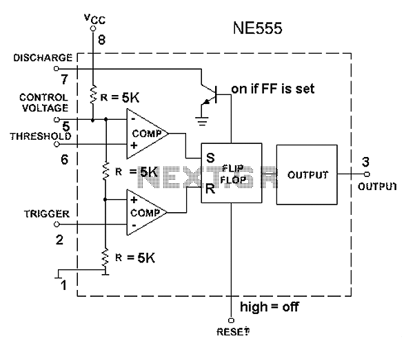
The 555 timer circuit, regardless of the manufacturer, has a consistent internal structure and performance. Various manufacturers produce different models of the 555 timer, including MC555, CA555, XR555, LM555, as well as domestic models like SL555, FX555, and 5G1555....
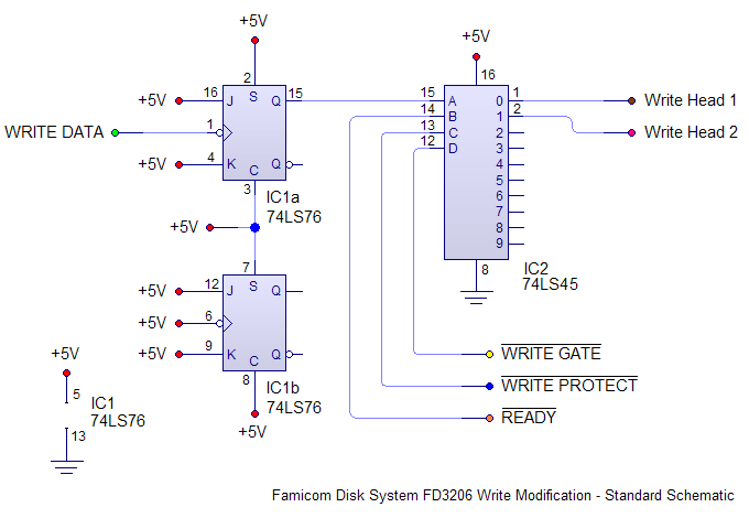
Install the new mod board into the FDS drive mechanism. This involves cutting two traces and soldering eight wires to various points on the board. If prior experience with console modchips exists, this task should be straightforward. The Famicom's...
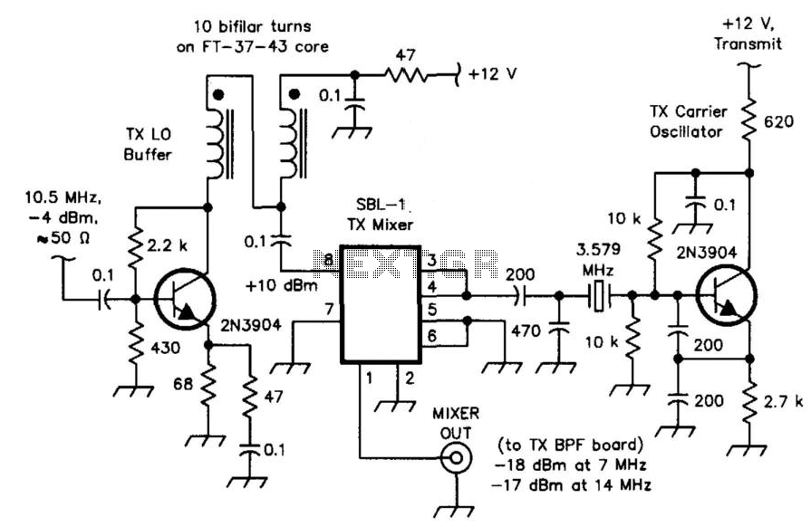
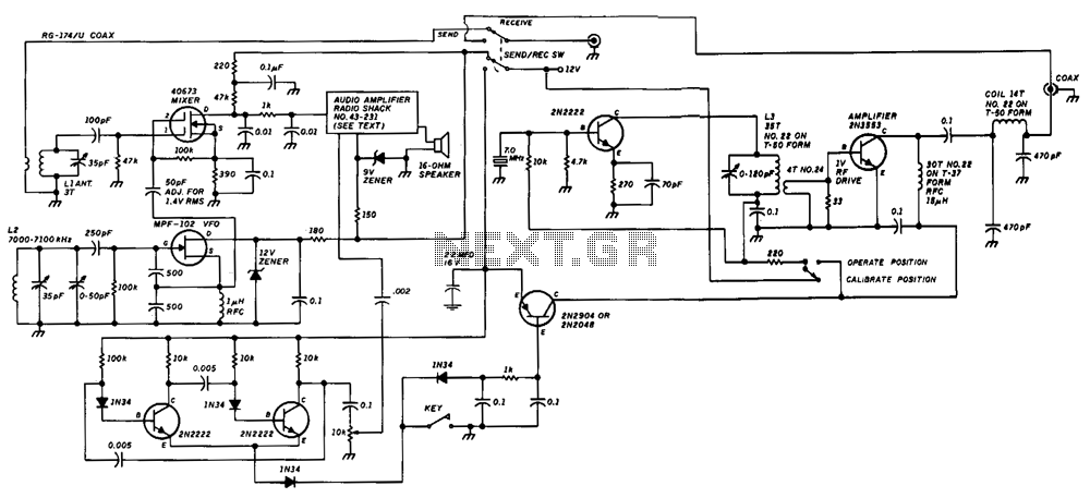
The transceiver mixer and carrier oscillator in the band-imaging (7- and 14-MHz) CW transceiver. Careful selection of drive levels and the use of a spectrally clean carrier oscillator ensure low spurious-signal content in the transmitter output. This transceiver mixer...

The relay power in the linear circuit is derived from a -120 V bias supply, while the transmit keying output from the Kenwood device is +12 V with a maximum current of 10 mA. A critical component of this...
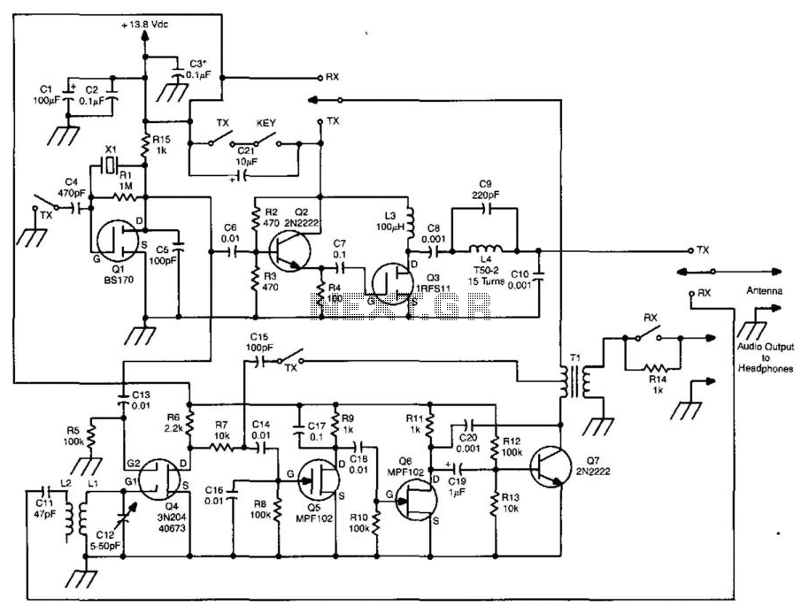
This transceiver features a three-stage transmitter and a direct-conversion receiver. The oscillator for the transmitter is controlled by Q1, with the frequency regulated by X1, which also functions as the local oscillator for the receiver. Buffer Q2 drives the...
The unit consists of a direct conversion receiver and a 1-W transmitter. The direct conversion receiver's voltage-controlled oscillator (VFO) is tuned slightly off frequency from the incoming signal. This frequency difference generates a clean, strong, and solid audio tone...