
Illumination Intensity Measurement System Diagram
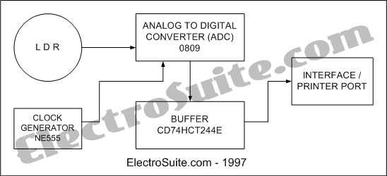
The illumination intensity measurement system is designed to accurately capture and process light intensity levels using a microprocessor-based approach. The system typically consists of several key components, including a light sensor, signal conditioning circuitry, an analog-to-digital converter (ADC), and a microprocessor for data processing and analysis.
The light sensor, which may be a photodiode or a phototransistor, converts the incoming light into an electrical signal. This analog signal is often weak and requires amplification. The signal conditioning circuitry is responsible for filtering and amplifying the signal to ensure it is within the optimal range for the ADC. This stage may include operational amplifiers and passive components to refine the signal quality.
Once the signal is conditioned, it is fed into the ADC, which converts the analog voltage levels into a digital format that can be processed by the microprocessor. The ADC's resolution and sampling rate are critical parameters that determine the accuracy and responsiveness of the illumination intensity measurement.
The microprocessor receives the digital data from the ADC and performs various calculations and analyses. It can display the illumination intensity on an output device, such as an LCD screen, or transmit the data to a computer or other devices for further processing. The microprocessor may also include firmware that allows for calibration, data logging, and communication with other systems.
Overall, the illumination intensity measurement system is an essential tool for applications that require precise light level monitoring, such as in environmental studies, photography, and architectural lighting design. The system's ability to provide real-time digital data enhances its utility in various fields where light intensity plays a crucial role.This is Illumination Intensity Measurement System Diagram. The data in the microprocessor is always in digital form. This is Illumination Intensity Measurement System Diagram - Part 1. The data in the microprocessor is always in digital form.. 🔗 External reference
Related Circuits
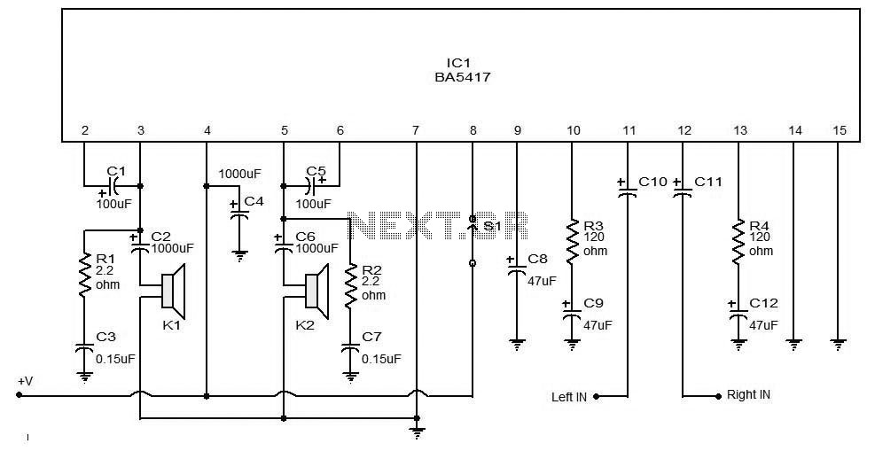
The BA5406 is a dual OTL (output transformerless) monolithic power integrated circuit (IC) featuring two high-output speaker amplifier circuits. It operates effectively with a supply voltage (Vcc) of 12 V and a load resistance (Rl) of 3 Ohms. At...
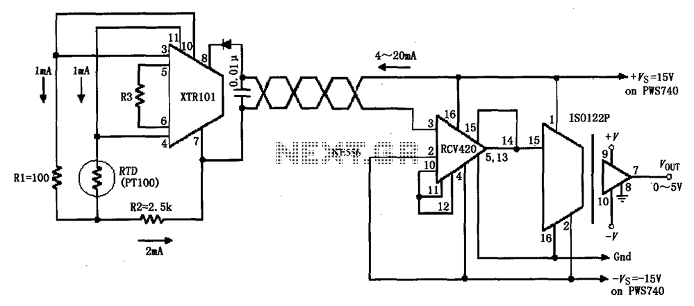
The circuit comprises an isolated RTD loop current configuration utilizing the XTR101 for transmitting loop current and the RCV420 for receiving it. The instrumentation amplifier detects changes in temperature via a resistance temperature detector (RTD), converting these changes into...
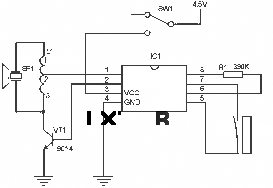
The alarm circuit operates as follows: When the power switch SW1 is turned on, the alarm system becomes active. If a magnet is brought close to the spring, the magnetic field attracts the spring, causing the dynamic and static...
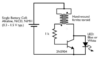
Tired of experimenting with capacitors? It's time to explore supercapacitors, which offer significant storage capabilities. This article provides instructions on building a small LED flashlight utilizing supercapacitors. A minimum voltage of 2 volts is necessary to illuminate the LED,...
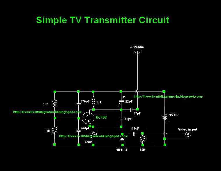
Many individuals inquire about TV transmitters. This document provides a useful circuit diagram that enables signal transmission over distances of 75 to 100 meters. The circuit diagram is not original; it was provided by a friend. Contributions of circuit...
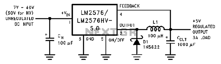
A wide range of 7 to 40V DC-DC step-down circuit that converts input voltage to 5V. This circuit operates as a buck converter, designed to efficiently reduce a higher DC voltage (ranging from 7V to 40V) to a stable output...