
Implementing A Sewing Machine Controller With An Mc9rs08ka2 Microcontroller
The MIC2199 synchronous buck switching regulator controller is designed to deliver high efficiency and robust performance in various applications, including power management for microcontrollers and other digital devices. The all N-Channel synchronous architecture significantly reduces conduction losses, making it suitable for high current applications. The ability to program the output voltage between 0.8V and 6V provides flexibility for different load requirements, while the wide input voltage range allows compatibility with various power sources.
The 300kHz switching frequency not only enables the use of smaller inductors but also contributes to the overall compactness of the circuit design. The external COMP pin is an essential feature, allowing designers to optimize the transient response by selecting appropriate output capacitors based on the application's specific needs. This adaptability is crucial in ensuring stable operation under varying load conditions.
While the absence of an external soft-start pin may initially seem limiting, the proposed method of implementing soft-start through the use of a capacitor and diode provides an effective solution. By connecting a capacitor (C1) and a 1N4148 diode between the VOUT and FB pins, the output voltage can be gradually ramped up, minimizing inrush current and preventing potential damage to connected components.
The output voltage waveform depicted in Figure 1 serves as a valuable reference for evaluating the performance of the MIC2199 in real-world applications. The observed overshoot and rise time characteristics are critical factors that engineers must consider when designing circuits to ensure reliability and efficiency. Overall, the MIC2199 is a versatile and powerful solution for applications requiring efficient voltage regulation and high output current capabilities.The MIC2199 is a synchronous buck switching Regulator controller. An all N-Channel synchronous architecture and powerful output drivers allow up to a 20A output current ca- pability. The MIC2199 operates from a 4. 5V to a 32V input and CAN be programmed for output voltage from 0. 8V to 6V. The 300kHz switching frequency allows the use of smaller ind uctor and the external COMP pin allows different output capacitor to be used for optimum transient response. To keep the pin count to a bare minimum, the MIC2199 does not offer an external soft-start pin that allow to reduce inrush current by delaying and slowing the output voltage rise time by connecting a capacitor on this pin.
Figure 1 shows the output voltage waveform for a stan- dard MIC2199 circuit that takes about 120 µs and exhibits an output voltage overshoot for VIN = 12V, VOUT = 3. 3V, I LOAD = 0A. Figure 2 shows a simple and inexpensive way of implementing external soft-start on the MIC2199 by using a capacitor, C1 and a Diode 1N4148 between VOUT and FB pins.
🔗 External reference
Related Circuits
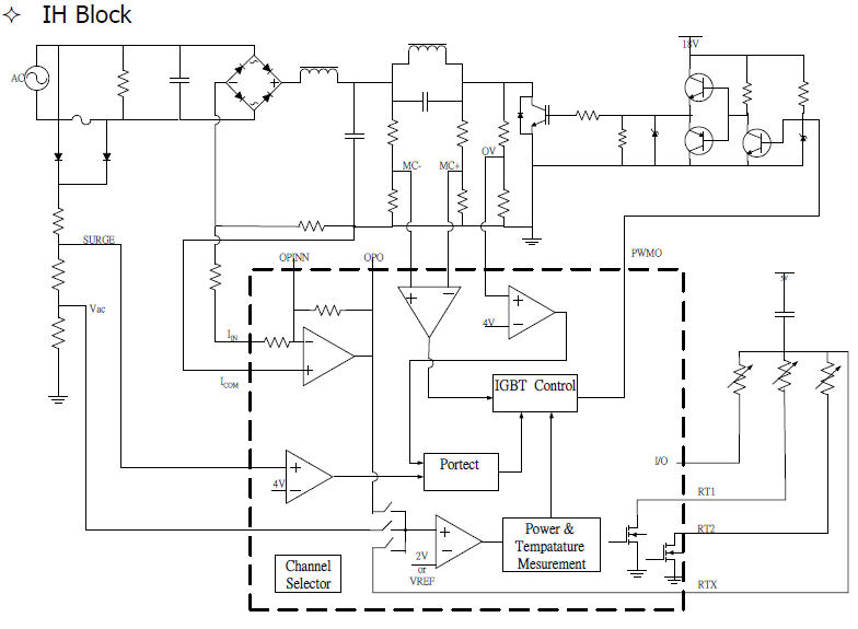
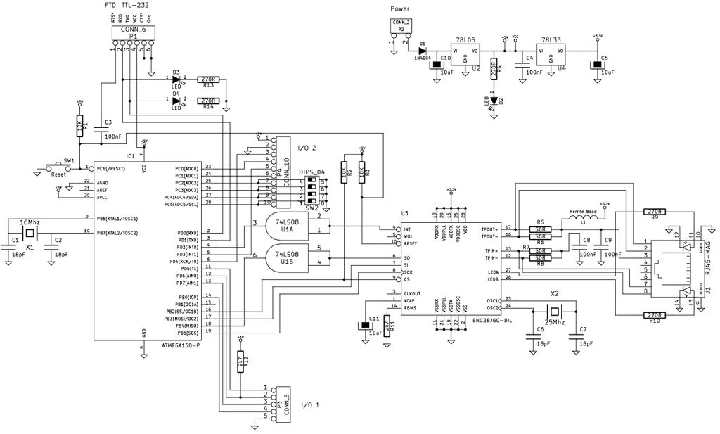
The control board features a 7-segment LED display for temperature and power readouts at the front. A fan is mounted at the base of the unit alongside an induction coil, which appears to use a similar gauge of Litz...
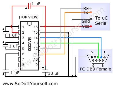
A device that provides a USB port is recognized as a "CP2103 USB to UART Bridge Controller" when connected to a Windows PC. According to the device documentation, it communicates in serial format at 38400 bps. The USB pinout...

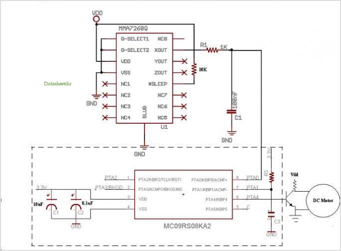
The microcontroller design features the microcontroller (MCU) in hibernation mode, which can only be awakened by a pulse (high-low-high) signal on the reset pin (active low). An accelerometer or an external real-time clock (RTC) serves as the wake-up source....
Motor Bike Headlight Controller Circuit. This circuit automatically turns a motorcycle's headlight on and off, independently of both the light and ignition switches, provided the battery is fully charged. The first stage... The motorcycle headlight controller circuit is designed to...
The Arduino is a simple and accessible controller platform suitable for various projects. A few months ago, an Ethernet shield was purchased for it. The Arduino platform is widely recognized for its user-friendly interface and versatility, making it a popular...
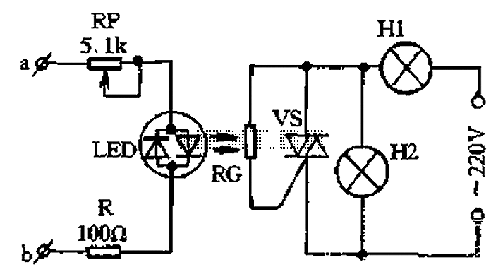
The circuit for a two-color music lantern controller is illustrated in Figure 1-44 below. Terminals a and b are located at both ends of the speaker, which receives audio signals. The audio signal is processed through a sensitivity adjustment...