
Improved 3 Transistor Audio Amp
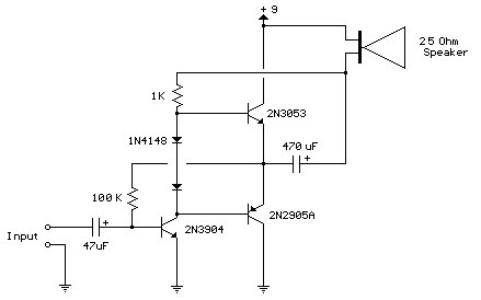
The improved three-transistor audio amplifier circuit is designed to enhance audio signal amplification while addressing common issues associated with traditional amplifier designs. The circuit typically consists of three transistors configured in a way that optimizes performance and minimizes distortion.
In this configuration, the driver transistor's load resistor is connected directly to the positive supply voltage. While this approach simplifies the circuit design and can improve response time, it introduces a potential drawback. As the output signal transitions positively, the voltage drop across the load resistor can lead to a reduction in the effective output swing, potentially limiting the amplifier's ability to handle dynamic audio signals without clipping.
To mitigate this issue, careful selection of the load resistor and biasing resistors is essential. The load resistor should be chosen to ensure that it provides sufficient current to the driver transistor while maintaining a balance between output power and linearity. Additionally, the use of feedback mechanisms can help stabilize the gain and improve overall linearity, further enhancing audio fidelity.
The overall architecture may also incorporate capacitive coupling at the input and output stages to block DC offsets and prevent unwanted biasing of subsequent stages. This ensures that only the AC audio signal is amplified, preserving the integrity of the audio signal throughout the amplification process.
In summary, the improved three-transistor audio amplifier is a robust design that leverages the advantages of direct load connection while addressing the inherent challenges associated with output voltage swings. Proper component selection and circuit design considerations are crucial for achieving optimal performance in audio applications.Improved 3 Transistor Audio Amp , The load resistor for the driver transistor is tied directly to the + supply. This has a disadvantage in that as the output moves positive, the drop across.. 🔗 External reference
Related Circuits
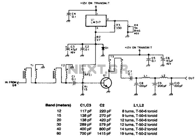
This linear amplifier provides a 10-W PEP output with a 1.25-W drive on the 10 m band. The transformers, T1, T2, and T3, consist of 10 turns of bifilar windings on an FT-50-43 toroidal core and are designed for...
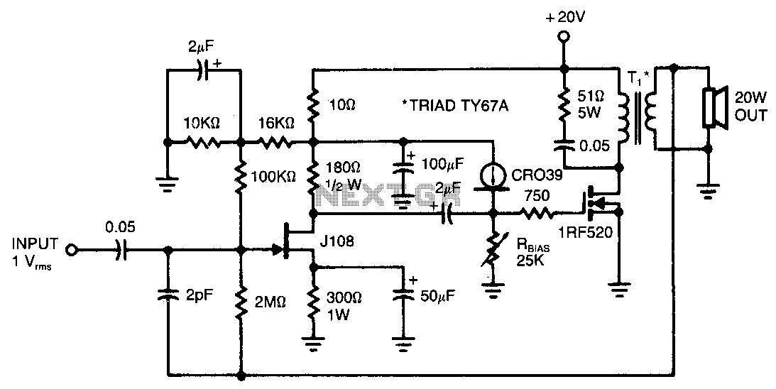
This amplifier provides 20 W of power to an 8-ohm load utilizing a single IRF520 transistor driving a transformer-coupled output stage. The design resembles the audio output stages commonly found in many low-cost radios and phonographs. Distortion remains below...
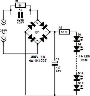
An array of white LEDs can serve as a compact lamp for living spaces. These LED lamps are commercially available and resemble standard halogen lamps, fitting into typical 230-V light fixtures. Upon inspection, it is evident that a capacitor...

This design can be used as a small booster. The amplifier is built around a balance stage. The quiescent current is set by diodes D1 and D2. The simplicity of the circuit, the quiescent current depends on the temperature...
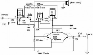
A 150W power amplifier circuit diagram utilizing power transistors TIP41, TIP142, and TIP147. The design is straightforward enough to construct without a printed circuit board (PCB). The power output range is approximately 100-150W. The 150W power amplifier circuit is designed...
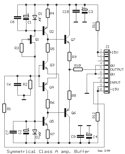
The circuit was designed to create a modular Class A buffer preamplifier to isolate stages in an audio circuit. BF245 is a general-purpose N-Channel JFET used in this design. The modular Class A buffer preamplifier serves as an essential component...
Warning: include(partials/cookie-banner.php): Failed to open stream: Permission denied in /var/www/html/nextgr/view-circuit.php on line 713
Warning: include(): Failed opening 'partials/cookie-banner.php' for inclusion (include_path='.:/usr/share/php') in /var/www/html/nextgr/view-circuit.php on line 713