
Increasing Regulator Current
The circuit utilizes a 78xx series voltage regulator, specifically the 7812, which provides a regulated output of 12V. This regulator is designed to handle a maximum output current of 1A under normal circumstances. However, for applications requiring higher current, a power transistor can be integrated into the circuit to augment the output.
In this configuration, the 7812 regulator maintains the output voltage by regulating the base of the power transistor, typically an NPN type such as the TIP3055 or similar, which is capable of handling higher currents. The base of the transistor is connected to the output of the 7812 through a resistor, which limits the base current. When the load current exceeds 650mA, the voltage drop across the 7812 causes the transistor to turn on, allowing it to supply additional current to the load.
The input voltage to the 7812 should be at least 2-3V higher than the desired output voltage to account for the dropout voltage of the regulator. In this case, with an input voltage of 20V, the regulator can effectively maintain a 12V output. The circuit must be designed with careful consideration of power dissipation; therefore, both the 7812 and the power transistor should be mounted on adequate heat sinks to prevent overheating, especially since the load is expected to draw up to 5A.
The overall circuit design should include bypass capacitors on the input and output of the 7812 to stabilize the voltage and filter out any noise. A common configuration would include a 0.33µF capacitor on the input side and a 0.1µF capacitor on the output side. Additionally, thermal protection measures should be implemented to safeguard against excessive temperatures, which could lead to thermal runaway or damage to the components.
The final assembly should be tested under load conditions to ensure that the voltage remains stable at 12V while the load draws the specified current, confirming the effectiveness of the power transistor in providing the necessary additional current.Although the 78xx series of voltage regulators are available with different current outputs, you can boost the available current output with this circuit. A power transistor is used to supply extra current to the load the regulator, maintaining a constant voltage.
Currents up to 650mA will flow through the regulator, above this value and the power transistor will start to conduct, supplying the extra current to the load. This should be on an adequate heat sink as it is likely to get rather hot. Suppose you use a 12v regulator, 7812. The input voltage should be a few volts higher to allow for voltage drops. Assume 20 volts. Lets also assume that the load will draw 5amps 🔗 External reference
Related Circuits
The circuit is designed to provide an output voltage range of approximately 1.25 to 13.5 volts when measured at the output. This circuit likely employs a variable voltage regulator or a similar topology that allows for a wide range of...
When the panel isn't generating, the entire circuit is off and there is absolutely no current drain from the battery. When the sun gets up and panel starts producing at least 10 Volt, the LED lights and the two...
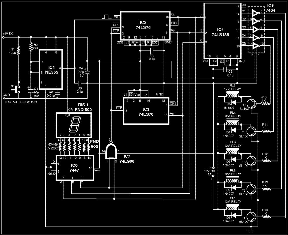
The circuit presented is a digital fan regulator that offers five speed levels, similar to conventional fan regulators. This ceiling fan controller utilizes readily available components. An optional 7-segment display with associated circuitry is included to show the selected...
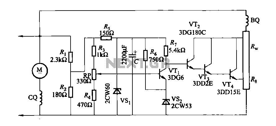
The DC generator automatic voltage regulator circuit is illustrated in Figure 7-53. This circuit is designed for a 40kW, 230V DC shunt complex machine, with a voltage change rate of up to 2.5 percent. In Figure 7-53, BQ represents...
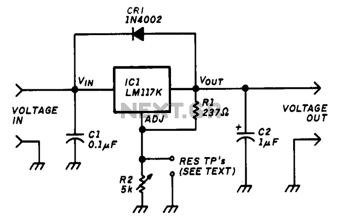
The variable voltage regulator allows for the adjustment of the output voltage of a fixed DC power supply between 1.2V and 37V DC, with the capability to supply output currents exceeding 1.5A. The circuit utilizes an LM117K three-terminal adjustable...
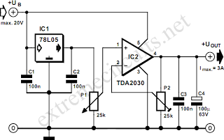
By combining a standard 78L05 voltage regulator with an integrated audio amplifier, specifically the TDA2030, it is possible to construct a simple yet effective adjustable voltage regulator. This regulator can output a voltage adjustable up to 20 V and...