
12V / 4A Solar cell regulator

The described circuit functions as a solar panel regulator, effectively managing the charging of a battery based on the voltage produced by the solar panel. The operational amplifier (U1) plays a critical role in monitoring the battery voltage, ensuring that the MOSFET remains off until the battery voltage reaches the predetermined threshold of 14.0V. The initial state of the circuit is inactive when the solar panel output is below 10V, preventing any current draw from the battery.
Once the solar panel generates sufficient voltage, the LED indicator activates, signaling that the charging process is in effect. The two small transistors are also engaged, providing necessary drive signals for the regulator circuit. The Schottky diode (D2) allows current to flow from the solar panel to the battery while preventing reverse current flow when the panel is not generating power.
Upon reaching the trigger voltage of 14.0V, U1 activates the MOSFET, effectively shorting the solar panel and ceasing the charging of the battery. This action is safe and prevents overcharging. The capacitor C2 then provides temporary power to the regulator circuit as it discharges, maintaining operation while the MOSFET is engaged. The discharge time of C2 is crucial, as it determines the OFF cycle duration of the regulator, typically around 3 seconds.
The circuit operates in a cyclical manner, alternating between charging the battery and discharging the capacitor. The duration of each ON cycle is variable, depending on the battery's current demand and any connected load. This design allows for efficient energy management, ensuring that the battery is charged optimally without exceeding its voltage limits.
Component selection is essential for maintaining the performance of the circuit. The TLC271 operational amplifier and LM385-2.5 voltage reference are specifically recommended due to their low power characteristics, which directly influence the regulator's efficiency. While other components can be substituted, caution is advised to avoid altering the circuit's behavior unintentionally.
The MOSFET should be chosen based on its RDSON rating to ensure minimal heat generation under maximum load conditions. The Schottky diode is preferred for its lower forward voltage drop, which enhances overall efficiency. The circuit is capable of handling solar panels up to 4 Amperes without requiring heat sinks, provided that the selected components are adequately rated for the application.
In summary, this solar panel regulator circuit effectively manages battery charging through a simple yet efficient design, utilizing widely available components that can be replaced with care to maintain functionality.When the panel isn't generating, the entire circuit is off and there is absolutely no current drain from the battery. When the sun gets up and panel starts producing at least 10 Volt, the LED lights and the two small transistors switch on.
This powers the regulator circuit. As long as the battery voltage stays below 14V, the operational amplifier (which is a very low power device) will keep the MOSFET off, so nothing special will happen and the panel current will go through the Schottky diode to the battery. When the battery reaches the trigger voltage, which is nominally 14.0V, U1 switches on the MOSFET. This shorts out the solar panel (a condition that is perfectly safe), the battery no longer gets charging current, the LED goes off, the two small transistors go off, and C2 powers the regulator circuit while slowly discharging. After roughly 3 seconds, C2 has discharged enough to overcome the hysteresis of U1, which switches the MOSFET off again.
Now the circuit will again charge the battery, until it again reaches the trigger voltage. In this way, the regulator works in cycles, with each OFF period being 3 seconds, and each ON period lasting for as long as necessary for the battery to reach 14.0V. The pulse length will vary according to the current demand of the battery and any load connected to it.
Building this circuit is very simple. All components are widely available, and most can be easily replaced by other types if necessary. I would not advice to replace the TLC271 nor the LM385-2.5 by different ones, unless you know very well what you are doing. Both of them are low power devices, and their power consumption directly defines the OFF time of the regulator.
If you use replacements that have a different power consumption, you will need to change the value of C2, adjust the biasing of Q3, and maybe even then you might run into unexpected trouble. The MOSFET can easily be replaced by any type you like, as long as its RDSON is low enough so that its dissipation will remain acceptable at the maximum current delivered by your panel.
For D2, basically any diode is acceptable as long as it can safely handle the total current produced by your panel. A Schottky diode like the one shown is an advantage because it will produce only half as much voltage drop as a standard silicon diode, and thus generate only half as much heat.
But a standard diode is perfectly suitable if properly sized and mounted. With the components shown, the regulator comfortably handles a 4 Ampere panel. For larger panels, only the MOSFET and diode need to be replaced by larger ones. The rest of the circuit remains the same. No heat sink is required for the power level shown. The indicated MOSFET can handle a much larger panel if fitted with a modest heat sink. The minimal ON time is given by the time C2 takes to charge up with the current limited by Q3 to roughly 40mA. This time is quite short, so this regulator can work down to very short pulses. 🔗 External reference
Related Circuits
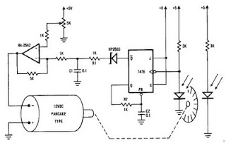
A simple encoder circuit for a DC motor can be constructed using the provided circuit diagram. The system includes the HA-2542 operational amplifier, a small 12 V DC motor, and a position encoder. During operation, the encoder generates a...
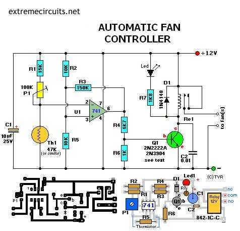
Transistor Q1 can be a 2N2222(A), 2N3904, NTE123A, ECG123A, etc. Not critical at all. It acts only as a switch for the relay so almost any type will work, as long as it can provide the current needed to...

This is a 12V 100mA transformerless power supply designed for low current applications. C1 is an X-rated AC capacitor that reduces peak AC voltage. D1-D4 are diodes that rectify AC to DC, and C2 is used to filter out...
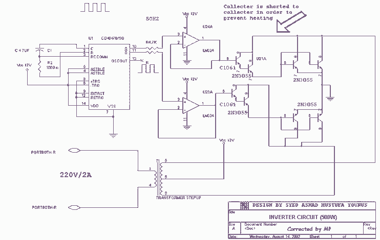
Using this circuit you can convert the 12V dc into the 220V Ac. In this circuit, 4047 is used to generate the square wave of 50Hz and amplify the current and then amplify the voltage by using the step...
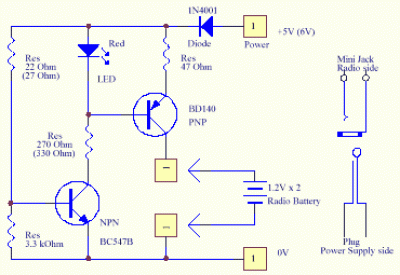
A solar cell radio utilizes a 3V power supply, which can be provided by either a single 3V battery or two 1.2V Ni-Cad batteries connected in series. The battery is non-removable, and the device features a mini jack socket...
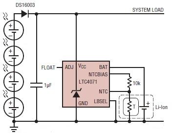
A simple solar-powered battery charger circuit can be designed using the LTC4071 Li-Ion/Polymer Shunt Battery Charger System with Low Battery Disconnect. When VCC reaches the programmed float voltage (4.1V with ADJ floating), the LTC4071 shunts excess current not used...