
Ind Meter Adapter
The schematic diagram for the Adapter is powered by a 9-Volt battery (B1), with an LM7805 regulator (IC2) providing a regulated 5-Volt source for the circuit. A switch (S2) controls the power. The core of the circuit consists of a 74HC132 quad Schmitt NAND-gate (IC1). The first gate (IC1-a) is configured as an oscillator, with its frequency determined by the RC components, including trimmer resistors (R6 and R7) in its feedback loop. The second gate (IC1-b) acts as a buffer/inverter, while the third and fourth gates (IC1-c and IC1-d) are configured as inverters, with one input of each tied to +5 Volts. The square-wave output from IC1-b is fed to pin 9 of IC1-c, which is also connected to J1, one of the test-inductor input terminals. When an inductor is connected across J1 and J2, the voltage at IC1, pin 9 remains high for a longer duration, depending on the inductance value. The output from IC1-c feeds into IC1-d, producing an average DC voltage across the output terminals (J3 and J4) that is directly proportional to the unknown inductance. Calibration is achieved through potentiometers R6 and R7 for high and low ranges, respectively, while potentiometer R1 sets the zero point on the DMM. After calibration with a known inductance and proper zeroing, the output voltage can represent inductance. Switch S1 allows for the selection of the Adapter's range, measuring from 3 µH to 500 mH in the low range and from 100 µH to 5 mH in the high range.
The Adapter circuit is straightforward to construct using point-to-point wiring. Alternatively, a PC board can be used, which can be etched from the provided foil pattern or ordered as a kit from the source mentioned in the Parts List.
PARTS LIST FOR THE INDUCTANCE METER ADAPTER
SEMICONDUCTORS
- IC1: 74HC132 Quad Schmitt trigger NAND gate, integrated circuit
- IC2: LM340T-5 (LM7805) positive 5-Volt regulator, integrated circuit
- D1: IN4148 diode
RESISTORS (All fixed resistors are 1/4W, 5%)
- R1: 1000 ohm trimmer potentiometer
- R2: 33,000 ohm
- R3: 220 ohm
- R4: 10,000 ohm
- R5: 100,000 ohm
- R6, R7: 10,000 ohm trimmer potentiometers
- R8, R9: 22,000 ohm
CAPACITORS
- C1: 0.01 µF monolithic
- C2: 0.1 µF monolithic
- C3: 0.001 µF monolithic
ADDITIONAL PARTS AND MATERIALS
- S1: DPDT switch, PC-mount
- S2: SPDT switch, PC-mount
- J1, J2: Spring-loaded terminal
- PL1, PL2: Banana Plug, red and black
- B1: 9V alkaline battery
- Printed-circuit materials, project enclosure, batteryAn inductance meter could be a valuable test instrument for a hobbyist to own. However few people own them because of the high price tags found on such instruments. That`s about to change. The Inductance Meter Adapter described in this articleis a circuit that, when connected to a digital multimeter (DMM), lets you measure low-valued inductances. The project can be built for a couple dollars, or less, depending on what parts are in your junk box. Or you can buy a kit of parts including a PC board from the source mentioned in the Parts List. The range of the Adapter is actually quite impressive. It allows your DMM to measure inductance from 3 microHenries to 7 milliHenries in two ranges. Basically, when the Adapter has an inductance connected at its input terminals, it develops a DC voltage at its output terminals that your DMM can measure and display as a calibrated inductance measurement. An analog multimeter cannot do the job because it`s input resistance is below the minimum 1-Megohm required for the adapter`s proper operation.
The Adapter certainly can`t replace a fine piece of test gear, but it`s a handy little instrument for sorting unlabeled parts, and matching inductors to one another. Another great feature of the Adapter is that you can have it working in less than an hour, with or without the kit.
CIRCUIT DESCRIPTION. The schematic diagram for the Adapter is shown in Fig. 1. The circuit is powered from a 9-Volt battery, B1, and an LM7805 regulator, IC2, provides a regulated 5-Volt source for the rest of ther circuit. Switch S2 turns the power on and off. The heart of the circuit is a single 74HC132 quad Scmitt NAND-gate IC1. The first gate in the package, IC1-a, is configured as an oscillator whose frequency is determined by the RC components (including trimmers R6 and R7) in its feedback loop; IC1-b is a buffer/inverter.
One input of both IC1-c and IC1-d is tied to +5 Volts, with both sections configured as inverters. The square-wave output from IC1-b is fed to the pin-9 input of IC1-c, and pin-9 also connects to J1, one of the test-inductor input terminals. When the inductor is connected across J1 and J2, the voltage input to IC1, pin 9 stays higher for a longer period, depending on the value of the inductor.
With the output of IC1-c feeding the IC1-d, the resulting average DC voltage across the output terminals (J3 and J4) is directly proportional to the unknown resistance. Potentiometers R6 and R7 calibrate the circuit for High and Low ranges, respectively, and potentiometer R1 sets the zero point on the DMM.
When the circuit is calibrated with a known inductance and properly zeroed out, the output voltage can represent inductance. Switch S1 selects the Adapter`s range; the circuit will measure from 3uH to 500mH in the Low range and from 100uH to 5 mH in the High range.
CONSTRUCTION. The Adapter circuit is simple enough to build using point-to-point wiring. However, if you prefer to use a PC board, you can etch your own from the foil pattern shown in Fig. 2, or order the kit from the source mentioned in the Parts List. PARTS LIST FOR THE INDUCTANCE METER ADAPTER SEMICONDUCTORS IC1 - 74HC132 Quad Schmitt trigger NAND gate, integrated circuit IC2 - LM340T-5 (LM7805) positive 5-Volt regulator, integrated circuit D1 - IN4148 diode RESISTORS All fixed resistors are 1/4W, 5% R1 - 1000 ohm trimmer potentiometer R2 - 33, 000 ohm R3 - 220 ohm R4 - 10, 000 ohm R5 - 100, 000 ohm R6, R7 - 10, 000 ohm trimmer potentiometers R8, R9 - 22, 000 ohm CAPACITORS C1 - 0. 01 uF monolithic C2 - 0. 1 uF monolithic C3 - 0. 001 uF monolithic ADDITIONAL PARTS AND MATERIALS S1 - DPDT switch, PC-mount S2 - SPDT switch, PC-mount J1, J2 - Spring-loaded terminal PL1, PL2 - Banana Plug, red and black.
B1 - 9V alkaline battery Printed-circuit materials, project enclosure, battery 🔗 External reference
Related Circuits
This wattmeter circuit has a measurement range of up to 1 kW. It is capable of providing complete (X)(Y) function with the use of only one transistor. The circuit is designed for operation with 117 Vac ±50 Vac. Modifications...
This circuit is designed as a portable unit that signals with an LED when the output waveform of a specific audio stage is "clipping," indicating that it is approaching its maximum permitted peak-to-peak voltage before an overload occurs. This...
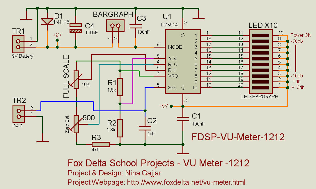
This simple VU meter can be utilized in a variety of projects. Since traditional electromagnetic VU meters are either no longer available or prohibitively expensive, this design employs the LM3914 integrated circuit and ten LEDs, allowing for versatile application...
This circuit provides a short circuit protected power supply from PC 12V supply voltage. This is particularly handy when working with PC interfacing projects. More: Fig-1 shows the circuit diagram of the complete power supply. The necessary 12V supply...
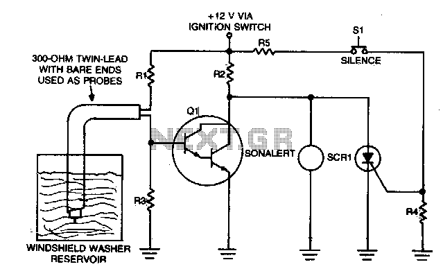
This circuit relies on the small current between two conductive probes suspended in a washer fluid reservoir. When the fluid level is below the probes, Q1 activates, and the Sonolert emits a sound. The circuit operates by utilizing two conductive...
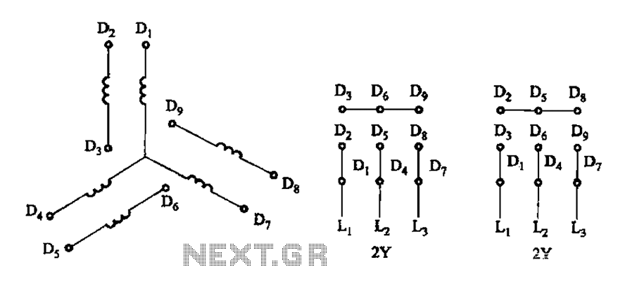
As illustrated in Figure 3-105, this diagram depicts the lead wiring configuration for a two-speed motor stator with a 2Y/2Y connection. The two-speed motor stator wiring diagram is essential for understanding the configuration and operation of the motor. In this...
Warning: include(partials/cookie-banner.php): Failed to open stream: Permission denied in /var/www/html/nextgr/view-circuit.php on line 713
Warning: include(): Failed opening 'partials/cookie-banner.php' for inclusion (include_path='.:/usr/share/php') in /var/www/html/nextgr/view-circuit.php on line 713