Johnson Counter
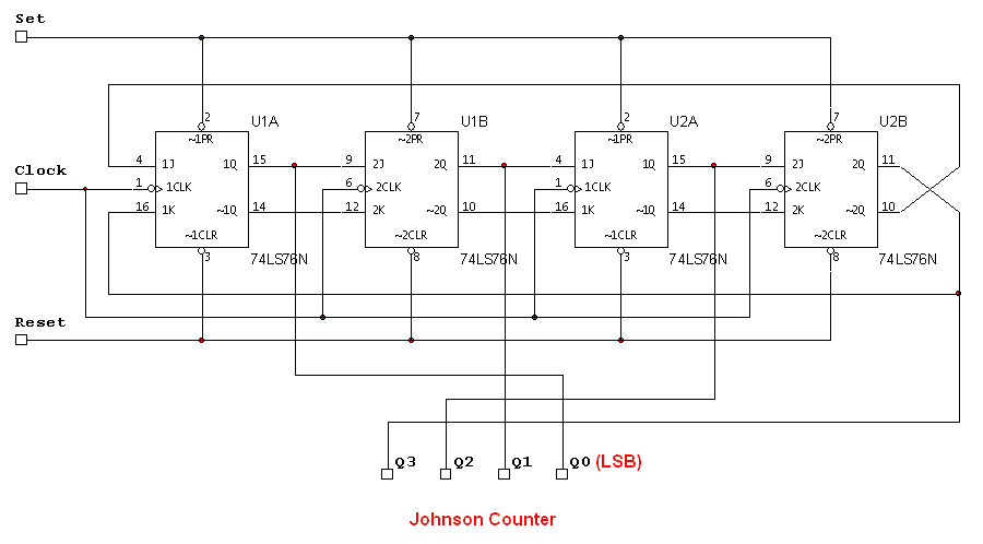
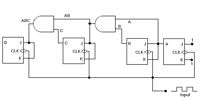
The attached schematic diagram is a Johnson Counter. Please provide advice on why "Loop 2" is considered to be invalid. Additionally, please suggest a few alternatives.
The Johnson Counter, also known as a twisted ring counter, is a type of digital counter that utilizes feedback from its output to produce a sequence of binary states. It is particularly efficient in terms of the number of flip-flops required to achieve a specific counting sequence. In a Johnson Counter, the output of the last flip-flop is inverted and fed back to the input of the first flip-flop, creating a unique counting sequence that is double the number of flip-flops.
In the context of the provided schematic, "Loop 2" may be considered invalid due to improper feedback connections or incorrect timing sequences that could lead to unintended states. In digital design, each loop or feedback path must maintain the integrity of the counting sequence. If the feedback does not adhere to the expected timing or logic levels, it can result in erroneous outputs, which may be the reason for the invalid designation.
To address the concerns regarding "Loop 2," it is advisable to verify the connections and ensure that the feedback path is correctly configured. Additionally, examining the timing diagrams can provide insight into potential timing issues that may affect the counter's operation.
Alternatives to consider might include using a different type of counter, such as a binary counter or a ring counter, depending on the specific application requirements. A binary counter can count in binary sequences and may be more straightforward to implement, while a ring counter provides a simpler counting mechanism with a defined number of states. Each type of counter has its advantages and disadvantages, and the choice should be based on the specific needs of the circuit design.Attached schematic diagram is a Johnson Counter. Would you pls advise while ""Loop 2"" is considered to be INVALID? Also, pls suggest few.. 🔗 External reference
