
Infra-Red Remote Control Tester
This infrared light tester circuit is a practical tool for evaluating the performance of remote control devices. The core component, the Schmitt trigger gate IC1f, is configured to amplify the weak signals received from the IRED, which serves as the sensor capable of detecting IR light. The choice of the LD274 diode is crucial, as it is sensitive to the specific wavelengths emitted by typical remote controls.
The R-C network, formed by capacitor C1 and resistor R2, plays a vital role in shaping the output signal. It ensures that the output LED, D2, does not remain continuously illuminated when exposed to steady IR sources, such as sunlight or artificial lighting. Instead, the circuit is designed to respond to pulse bursts, which are characteristic of remote control signals. This design allows for a clear indication of whether a remote control is functioning correctly, as the LED will light up momentarily in response to valid IR signals.
The sensitivity of the circuit is optimized to detect IR signals from distances of up to 50 cm, making it suitable for general testing applications. The low power consumption of the circuit, drawing less than 1 mA during operation and virtually no current in the absence of IR light, enhances its usability. This efficiency means that the tester can remain in a ready state without the need for manual power management, such as an on/off switch.
The compact design of the circuit allows it to be enclosed in a small ABS case, which provides protection and portability. The construction drawing serves as a guide for assembling the components securely within the enclosure, ensuring ease of use and accessibility for anyone needing to test remote control devices. Overall, this circuit is a valuable addition to the toolkit of anyone working with infrared remote controls, providing a quick and reliable method for performance verification.This little circuit is invaluable for quick go/no-go testing of just about any remote control transmitting infra-red (IR) light. The tester is battery-powered, built from just a handful of commonly available and inexpensive parts, and fits in a compact enclosure.
Schmitt trigger gate IC1f is used as a quasi-analogue amplifier with, unusually, an i nfra-red emitting diode (IRED) type LD274 acting as the sensor element. An R-C network, C1-R2, is used at the output of the gate because all IR remote controls transmit pulse bursts, and to prevent the output LED, D2, lighting constantly when day-light or another continuous source of IR light is detected. This creates a useful quick test` option: point the tester at direct daylight, and the indicator LED should light briefly.
The sensitivity of the tester is such that IR light from remote control is detected at a distance of up to 50 cm. The circuit is designed for very low power consumption, drawing less than 1 mA from the battery when IR light is detected, and practically no current when no light is detected.
Hence no on/off switch is required. The construction drawing shows how the tester may be cased` using a small ABS case from Conrad. 🔗 External reference
Related Circuits
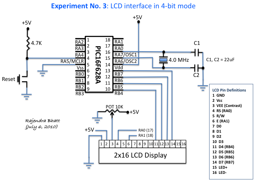
An HD44780 Character LCD is a liquid crystal display (LCD) device designed for interfacing with embedded systems. These screens are available in various configurations, including 8x1 (one row of eight characters), 16x2, and 20x4. The most commonly produced configuration...
The circuit utilizes a 4-bit encoder to generate data, which is then modulated using an RF modulator for transmission. On the receiving end, the signal is demodulated, and a decoder retrieves the 4-bit data. The pin configuration for the...

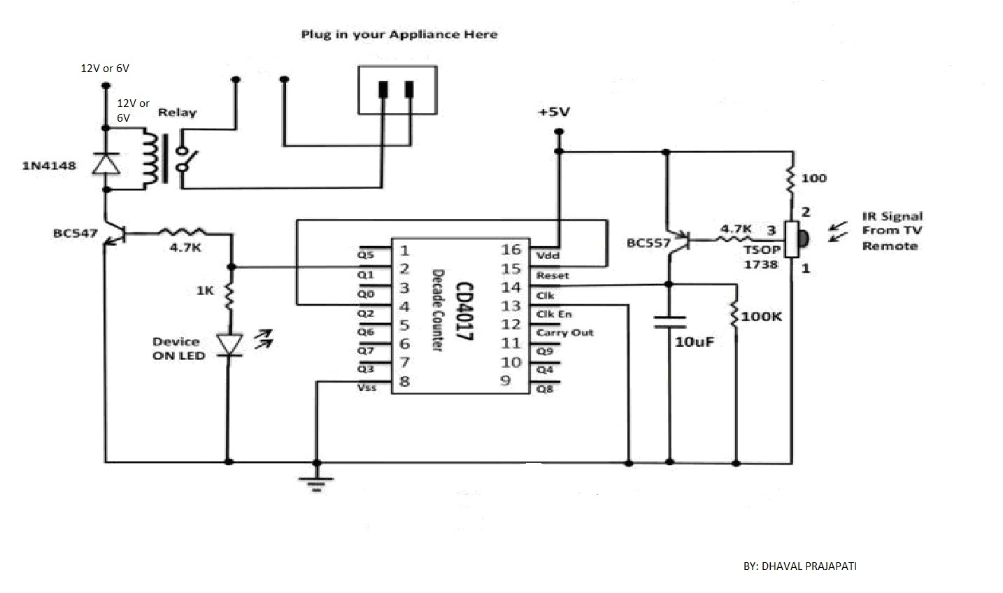
Most homes today have at least a few infrared remote controls, whether for the television, video recorder, stereo, etc. Despite this, many people have experienced frustration with lights that remain on after settling into a comfortable chair to watch...
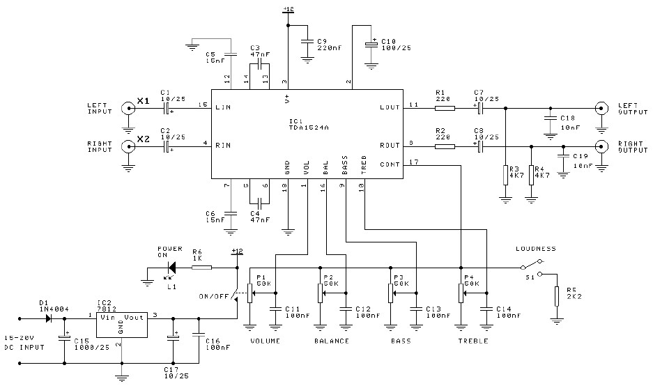
Preamplifier and tone control circuit based on the TDA1524A. The tone control circuit module is included in this preamplifier circuit, allowing for direct connection of the output channels to a stereo power audio amplifier circuit. This RIAA stereo preamplifier...
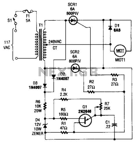
The speed-control switch provides effective control and stability across its entire operating range. This circuit utilizes two SCR devices arranged in a full-wave configuration to manage the DC power supplied to a motor. A center-tapped transformer is employed to...
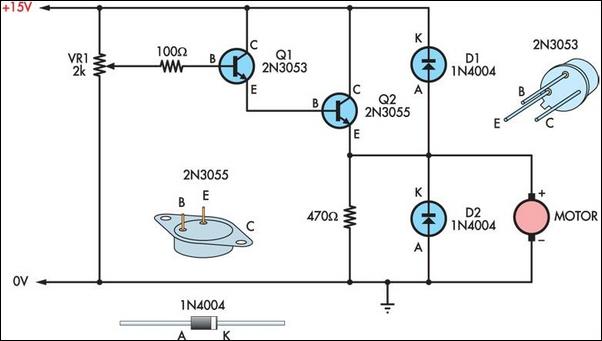
Two simple 12V DC motor speed controllers can be constructed for a minimal cost. These controllers take advantage of the principle that the rotational speed of a DC motor... DC motor speed controllers are essential components in various applications where...
Warning: include(partials/cookie-banner.php): Failed to open stream: Permission denied in /var/www/html/nextgr/view-circuit.php on line 713
Warning: include(): Failed opening 'partials/cookie-banner.php' for inclusion (include_path='.:/usr/share/php') in /var/www/html/nextgr/view-circuit.php on line 713