
Infra Red TV Remote Control Extender
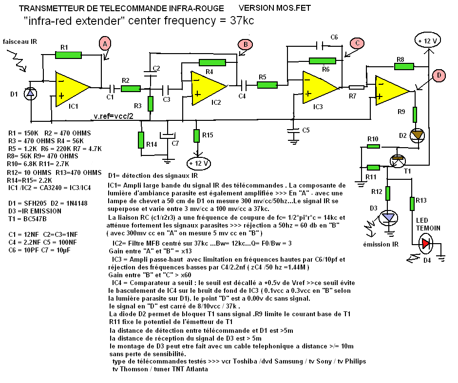
The circuit designed by Mr. Guy Bocquillon employs a 37 kHz active filter, which is crucial for applications such as infrared communication. The primary components include a photodiode, which detects the infrared signals, and operational amplifiers (op-amps) sourced from Texas Instruments. The choice of a 37 kHz frequency is significant, as it is commonly used in remote control systems for various electronic devices.
To ensure optimal performance and to mitigate the risk of unwanted oscillations at the operating frequency, it is recommended to incorporate a shielding mechanism around the photodiode (D1) and the operational amplifiers (IC1 and IC2). This shielding can be achieved using a grounded metal enclosure or a conductive material that effectively blocks external electromagnetic interference.
The schematic itself, originally created using MS Paint, illustrates the circuit layout, including the connections between the photodiode, op-amps, and other passive components. The design may include resistors, capacitors, and possibly inductors, which are critical for establishing the desired filter characteristics and ensuring signal integrity.
In addition to the circuit's primary function, it is noted that the design can be adapted for various applications that utilize a 37 kHz modulating frequency, making it versatile for integration into different systems. The forthcoming release of schematic components for the Open Office Drawing program will enhance accessibility for engineers and hobbyists alike, allowing for easier modifications and adaptations of the circuit design. The components will be presented in color, improving visual clarity and aiding in the understanding of the circuit's operation.This circuit was sent to me by Mr Guy Bocquillon from France. Now retired, and in his seventies, Mr Bocquillon keeps himself active in his hobby and his results and support are most appreciated. The notes on the schematic are in French as Mr Bocquillon`s english is not too good. After buildiing both my Mark 1 and Mark 2 circuits, Mr Bocquillion ha s mafe an improoved version, which is working very well. His design is based on an active filter, centered at 37KHz modulating frequency and uses a photodiode and op-amp from Texas Instruments. Mr Bocquillion also says that after plenty of tests for his pleasure (because my job is became my hobby) he has made this circuit which is working very well.
It is just necessary to built a sheild around D1 and IC1/IC2 to avoid risks of oscillations around 37kHz. I would like to point out that this circuit will also work with any other appliance using 37kHz as the IR modulating frequency.
The original artwork was done in MS Paint, and as you can see is a very capable circuit. I will be releasing some schematic components I have made for Open Office Drawing program later this year onto my site. These can be used to draw schematics and will be available in colour for clarity. 🔗 External reference
Related Circuits
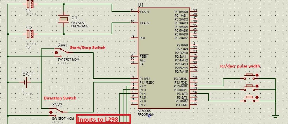
Greetings to all! A new user is exploring microcontrollers and is utilizing the AT89C55WD microcontroller to control an H-Bridge (L298), which subsequently drives a DC motor. The circuits for this setup are... The AT89C55WD microcontroller is an 8-bit microcontroller from...
220V mains electricity is sent through a 0.33 µF capacitor (Ci) and a 50 kΩ resistive drop. A bridge rectifier composed of diodes D1 to D4 converts the AC voltage to DC. After passing through a 100 µF capacitor...
The incandescent light bulb has been the leading choice for lighting applications since its introduction in the late 19th century; however, its efficiency has consistently remained below five percent. Growing global ecological awareness and the demand for more cost-effective...
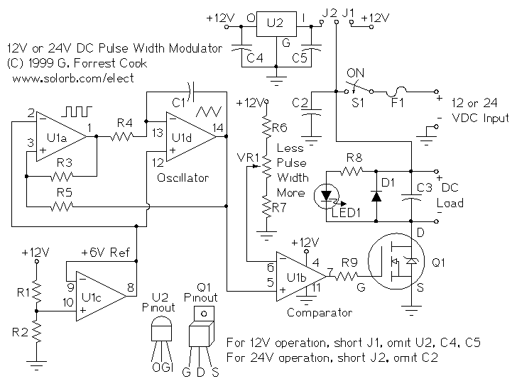
PWM is a device that can be utilized as an efficient light dimmer or DC motor speed controller. Function: for a general-purpose device that can... PWM (Pulse Width Modulation) is a versatile technique widely employed in various electronic applications, particularly...
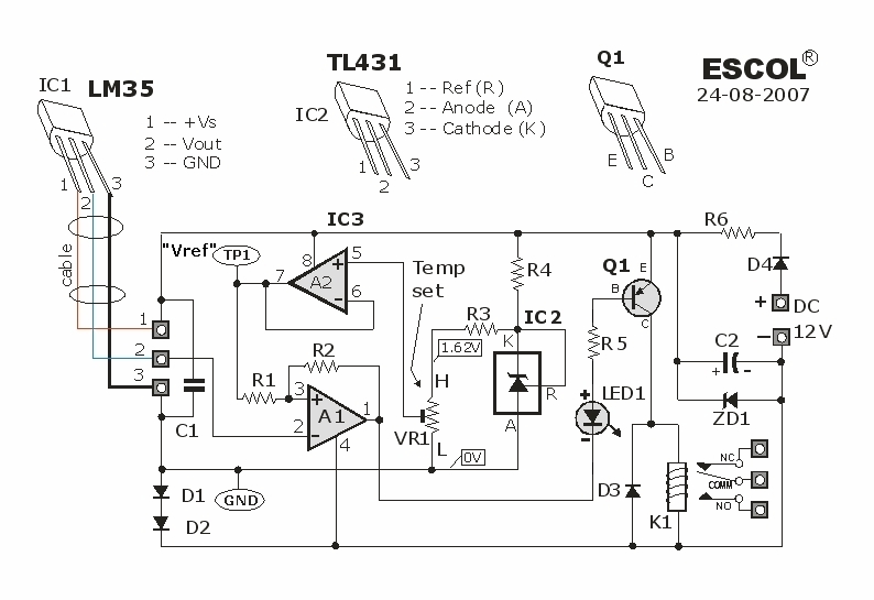
This temperature-controlled relay circuit is a simple yet highly accurate thermal control circuit that can be used in applications where automatic temperature regulation is required. The temperature-controlled relay circuit operates by monitoring the ambient temperature using a temperature sensor, such...
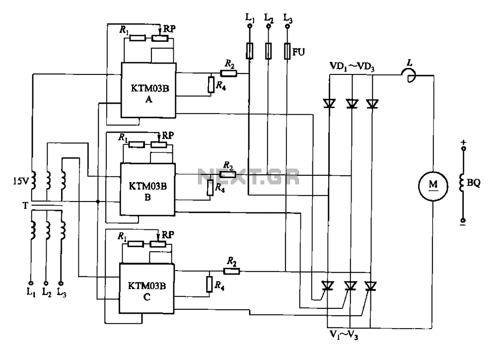
Adjusting the phase potentiometer RP can change the conduction angle of each corresponding thyristor (V1-V). This adjustment alters the voltage applied across the load. The circuit utilizes a phase control technique to manage the power delivered to a load by...