
AN6610 Application Circuit
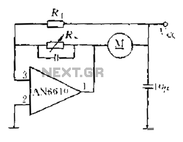
The AN6610 application circuit is designed for precise motor speed regulation in response to variations in supply voltage and mechanical load. The circuit utilizes feedback control to ensure that the motor operates at a consistent speed, despite external disturbances.
The operation begins with the detection of changes in the supply voltage (Vcc) which can occur due to fluctuations in the mechanical load applied to the motor. These changes lead to variations in the back EMF generated by the motor, which directly influences the motor speed.
To monitor these variations, the circuit employs an adjustable resistor network (R1, R4) that samples the voltage across the motor. This sampled voltage is crucial as it reflects the instantaneous operating conditions of the motor. The error amplifier receives this sampled voltage at its inverting input and compares it with a predetermined reference voltage (VREF) at the inverting input.
The difference between these two voltages generates an error signal, which is processed by the error amplifier. The output of the error amplifier is connected to the base of a transistor that acts as a control element for the motor's supply voltage. By adjusting the base current of the transistor, the output voltage at pin 3 is modulated, allowing for real-time adjustments to the motor's operating conditions.
The feedback mechanism established in this circuit creates a negative feedback loop that stabilizes the motor speed. When the motor speed deviates from the desired setpoint, the error amplifier responds by altering the output voltage, thus correcting the speed. This closed-loop control system is essential for applications requiring precise motor control, ensuring that the motor maintains a consistent performance under varying load conditions.
Overall, the AN6610 application circuit provides an effective solution for motor speed control, leveraging the principles of feedback and error amplification to achieve reliable and stable operation.AN6610 Application Circuit It works briefly as follows: When the supply voltage vcc motor mechanical or negative change when the load changes, can cause changes in motor speed. And speed proportional to the anti-electric potential E. Marrow also change accordingly the voltage across the motor also changes. From adjustable resistor 1, 4 on two sampled voltage v ,. Reflects these voltage changes, delivered to the error amplifier inverting input terminal, compare it with the inverting input of the reference voltage VREF, the error amplifier controls the two rear base of the transistor, the output voltage (pin 3) is adjusted. 3-pin output voltage and V.. There was a negative relationship between the feedback control, the results tend to be closed-loop control to maintain a constant speed.
Related Circuits
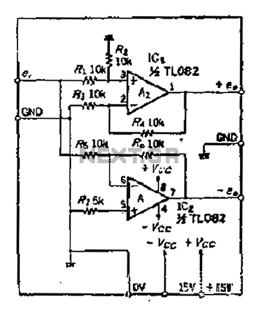
A balanced output is often associated with the positive phase amplifier output terminal of an operational amplifier, which is typically viewed as the inverting amplifier circuit. However, the reversed phase output can lead to a loss of balance in...

The phase and neutral wires from the power source have already been connected to electrical appliances such as fans and light points. According to the UPS connection diagram, an additional phase wire should be connected to those appliances where...
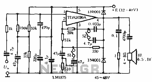
This circuit features bass boost compensation for a practical power amplifier. It is important to adhere to the specified parameters of the amplifier circuit elements. When switches S1 and S2 are disconnected, the bass boost function can be set...
This is a car alarm simulator that uses an LED as a simulation output. This simple circuit can indicate whether a car is running or not by detecting the voltage difference when the car is on or off. This...
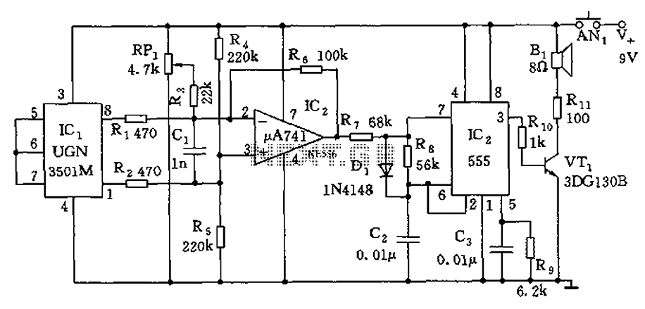
The circuit consists of a 555 timer and associated components designed for voltage-to-frequency conversion. It is utilized for determining the orientation of Earth's magnetic field using a Hall-effect sensor, specifically the UGN-3501M. This sensor incorporates a Hall element and...

The metal detector circuit presented here exemplifies simplicity while demonstrating effective functionality. It utilizes a single 40106 hex Schmitt inverter IC, a capacitor, a search coil, and batteries. A connection from IC1b pin 4 must be made to a...