
pic based pid motor control proteus simulation ii

The schematic design consists of two primary pages: the first detailing the main control and operational circuitry, while the second provides the necessary support for simulation purposes. The main control circuitry is responsible for managing accessory relays and indicators, as well as executing the control loop that regulates the throttle control circuit. The throttle control is achieved through a stepper motor, which is shown in the schematic to illustrate the movement of the step angle as the PID controller adjusts to reach the desired setpoint.
Timing is critical in this design, with an interrupt routine set to trigger every 1 ms. This timing allows the PID control algorithm to be executed every five counts, ensuring that the motor's speed is accurately monitored through TMR1 counts and overflow signals. The RPM of the motor is continuously captured within the main loop to provide real-time feedback for the control system. The control routine operates on a 250 ms interval, which is designed to accommodate the inherent lag caused by motor inertia during simulation.
In this application, active braking is not implemented, as the motor is intended to simulate the behavior of an internal combustion engine. Instead, the system relies on throttle reduction as a means of deceleration. The throttle control circuit is executed through a dedicated PIC microcontroller, which translates STEP and DIR pulse signals into unipolar drive signals for the stepper motor, utilizing an H-bridge configuration for efficient control.
Additionally, the support circuitry incorporates an indexer that counts the STEP pulses emitted by the control routine and converts these pulses into an analog voltage that drives the simulated motor. This approach is specifically chosen to eliminate the complexity associated with PWM control, which is common in similar designs. The adjustments made to the control algorithm during simulation have yielded improved RPM control, indicating a more effective response to varying load conditions and desired performance metrics.
Overall, this schematic provides a comprehensive overview of a stepper motor control system designed for simulation, highlighting the integration of various components and the implementation of control algorithms to achieve precise motor operation.The first schematic page contains the primary content of the design while the second page contains simulation support circuitry. The primary design controls the accessory relays and indicators. It also drives the control loop and makes adjustments to the throttle control circuit. For this publication, the menu control and the NV storage control is not provided. The throttle control stepper motor is shown on this page in order to see the step angle move while the PID is seeking the setpoint. The timing architecture sets the interrupt() routine for 1ms. (5) counts signal the PID routine to run from the main loop. The motor speed is captured through TMR1 counts and overflows. RPM is captured in the main loop. The control routine, which responds to new PID control calculations, runs at 250ms intervals. Because the simulation accounts for motor inertia, there is lag in the applied control signal and motor response, the design attempts to temper this by applying the throttle control every 250ms.
In this design there is no active braking as the motor is supposed to be an internal combustion engine, so removing throttle is the braking in this application. The throttle control circuit is implemented as an independent PIC that converts STEP and DIR pulses into uni-polar stepper motor drive signals via the H-bridge.
This design is actually a working stepper motor design. The support circuitry also includes an indexer that that counts the STEP pulses and converts them into the analog drive voltage for the simulated motor. As mentioned in previous posts, this implementation is for simulation reasons in order to avoid PWM control, normally found in such designs.
After experimenting a bit with the simulation, I made some changes to the control algorithm included below. In the simulation, they seem to give a better degree of control of the RPM. /* * You can use this source code anyway you like. All that is asked is to leave any * existing attributions in place. * Also, please link back to the-project-place. com. If you are so inclined, * please leave a comment for the project at the-project-place. com */ #include "mappings. h" #include "db. h" #define FALSE 0 #define TRUE 1 #define UP_BUTTON 0 // base board buttons #define DOWN_BUTTON 3 #define UP_BUTTON_PORT PORTB #define DOWN_BUTTON_PORT PORTB #define CCW 0 #define CW 1 void Uart_TX_const( const UCHAR *s, UINT8 i); void Uart_TX( UCHAR *s, UINT8 i); void putc(UCHAR c); void puts(UCHAR *s); UCHAR getc(); void nl(); unsigned int getuint(void); void SendChrRepeat(UCHAR c, UINT8 n); BOOL processCommand(void); void CONTROL_machine(); void BUTTON_machine(); void KILL_machine(); void MENU_machine(); void doMOVE(UCHAR steps); BOOL decreaseThrottle(); BOOL increaseThrottle(); void dosample(); void dosample2(); void display(); void LEDz(); void init(); typedef struct { UP : 1; DOWN : 1; SEL : 1; DIR : 1; runFlag : 1; MANUAL : 1; S : 1; LIMIT_MIN : 1; LIMIT_MAX : 1; LIMIT : 1; KILL : 1; START : 1; } STATE_BITS; STATE_BITS state; typedef struct { UINT8 state_KILL_MACHINE; UINT8 state_MOVE_MACHINE; UINT8 state_SAMPLE_MACHINE; UINT8 state_DISPLAY_MACHINE; UINT8 state_CONTROL_MACHINE; } SM_STATES; SM_STATES state_sm; typedef struct { LIMIT : 1; UP : 1; DOWN : 1; SEL : 1; START : 1; KILL : 1; } INPUT_BITS; INPUT_BITS inputs; extern DBNV db; const UCHAR hello[] = "Hello World Engine CTL Test "; UINT8 buf[32]; UCHAR *str; /// /// interrupt /// UINT16 t1_ovflw = 0; UINT16 tick = 0; bit doPID_bit; UINT8 xcnt= 5; #define TICKCOUNT 400 #define TMR0_RELOAD 194 // 1ms tick #define CONTROL_RELOAD 250 UINT8 ycnt = CONTROL_RELOAD; bit doControl_bit; /// /// sample /// void dosample(); UINT32 sample, sample0, sample1; UINT32 samples; UINT16 capL, capH; UINT32 rpmtime; UINT16 rpm, rpm0, rpm1; bit u; bit v; /// /// pid /// void doPID(); UINT16 targetRPM; INT16 newRPM; INT16 e0, e1, e2, e3; INT16 Se, I, dD; INT32 Cn; #define satMAX 31 UCHAR stepCounter; UCHA
🔗 External reference
Related Circuits
Variable-gain amplifiers (VGAs) can be used in many types of systems, such as radio receivers. In this system, the input signal voltage depends on an. Variable-gain amplifiers (VGAs) are integral components in various electronic systems, particularly in radio receivers where...
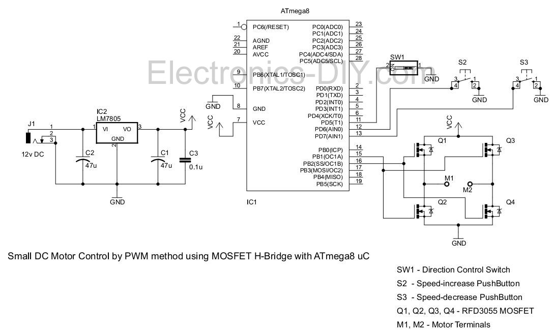
This project involves controlling a small DC motor, sourced from an old personal cassette player, using the ATmega8 microcontroller. The ATmega8 features three PWM channels, of which two are utilized in this application. The PWM signals are sent to...
Figure 2-32 (a) illustrates the time control diagram for a motor operated by switch S1. When S1 is set to position 1, the power driver circuit supplies current to the motor, enabling it to run. When S1 is switched...
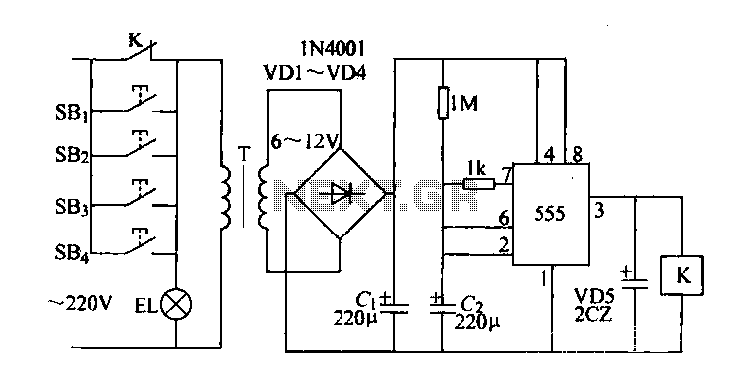
Control buttons SB1 to SB4 can be installed in various positions within a corridor. By pressing any one of these buttons, the EL horse lights will turn on. After releasing the button, the transformer and rectifier supply power to...
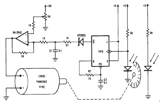
A simple encoder circuit for a DC motor can be constructed using this circuit diagram. The system consists of the HA-2542, a small 12-V DC motor, and a position encoder. During operation, the encoder generates a series of constant-width...
This inverter circuit can provide a stable 230V output voltage. The operating frequency is determined by a variable resistor (VR1) and is typically set to 60 Hz. Various off-the-shelf transformers can be utilized, or custom-wound transformers can be created...