
Infrared Fire-Cracker Igniter
The described circuit utilizes a remote control ignition system for firecrackers, enhancing safety by allowing the operator to maintain a safe distance during detonation. The core components include an infrared receiver (TSOP1738), a monostable multivibrator (IC1), and a relay (RL1) to control the high current required to ignite the firecracker. The circuit is designed to be powered by a 12V battery, providing a reliable power source while ensuring the system remains portable.
The use of a monostable multivibrator allows for a timed output that ensures the relay remains activated long enough to heat the heater element (R7) to ignition temperature. The choice of a heater element with a resistance of 3 to 3.5 ohms ensures that sufficient current flows through it to generate the necessary heat. The circuit's design prioritizes safety, as the metallic enclosure protects against accidental ignition and ensures durability against the harsh conditions of firecracker use.
The IR receiver is strategically positioned to receive signals from the remote control, allowing for user-friendly operation. The inclusion of LEDs serves dual purposes: they provide visual feedback on the circuit's status and indicate when the firecracker is about to detonate, thereby alerting the user to retreat to a safe distance.
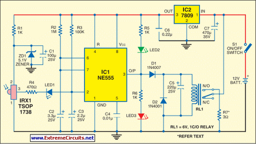
For optimal performance, it is essential to select components that can withstand the electrical demands of the circuit. The relay must be rated for at least 5 amperes to handle the current flowing through the heater element, and the wiring should be appropriately gauged to prevent overheating. The entire system should be tested thoroughly to ensure reliability and safety before actual use.Firecrackers are normally ignited by using a matchstick or a candle. You have to run away quickly after igniting the fuse of the firecracker. This method of igniting firecracker is unsafe, because the danger of the firecracker bursting before you reach a safe distance is always there. The device described here uses remote control, usually used wit h TV receivers or CD players, to burst the fire-cracker. Thus the firecracker can be ignited from a safe distance using the circuit described below in conjunction with the remote control. In the diagram shown here, normally the output of IC1 is low and green LED2 is on` and the red LED3 off.
` This indicates that the circuit is ready for use. When any key on the remote control is pressed, output pin 3 of IRX1 (IR receiver module TSOP1738) goes low. This output is connected to pin 2 of IC1 via LED1 and resistor R4 to trigger the monostable operation of IC1.
The output of IC1 remains high for a period equal to 1. 1G—R2G—C2. With the values of the components given in the circuit diagram here, the period works out to 3. 5 seconds approximately. This activates relay RL1 and red LED3 glows and green LED2 turns off. On` state of red LED3 indicates that the firecracker is about to burst. R7 is a small part of the element of an electric heater (220V, 1000W), which is kept away from the electronic circuit and connected to the relay contacts through a thick electric cable. The resistance value of short length of the heater element (R7) is 3 to 3. 5 ohms. A current of around 4 amperes flows through it when connected to a 12V battery. Flow of 4A current through R7 for 3. 5 seconds makes it red hot, which ignites the fire-cracker. The circuit is powered by a 12V, 7AH battery. IC2 provides about 9V for the operation of the circuit. The circuit should be housed in a metallic cabinet to prevent it from being damaged by bursting of the firecracker.
The IR receiver and the two LEDs should be fixed on the front panel of the cabinet. Wiring and relay used in the circuit should be chosen such that they are able to carry more than 5 amperes of current. 🔗 External reference
Related Circuits
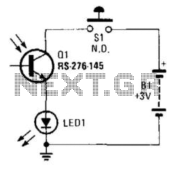
Using a battery, a phototransistor, and a visible-light LED, this simple circuit functions as a "go/no go" tester for infrared remote control devices. The illumination of the LED indicates that the phototransistor is being modulated by infrared energy. This circuit...
This is the latest version of the Improved Infrared Receiver with Status LED which can control any desktop PC with an ordinary remote control. The project comes along with a small PCB in order to save space. It connects...
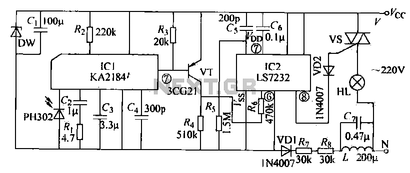
The receiving circuit operates as follows: when the infrared receiver detects a signal from the remote control transmitter, the KA2184 processes this signal, resulting in a low output at the pin. This low output is directly connected to the...
An infrared motion detector alarm is designed to activate whenever a person enters its infrared detection zone. This sensor detects the movement of a human body, triggering an automatic alarm. The detection zone has a horizontal coverage of 80...
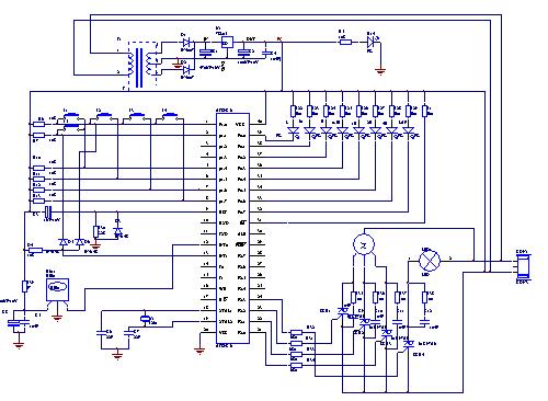
The electric fan with remote control underwent extensive research and development in the Pearl River Delta area of Guangdong during the early 1990s. It utilizes a specialized mask chip that serves as the primary management chip. A systematic scheme...
Having to use the infrared remote control, we will procure in addition to modulate the Nutchip infrared receiver. Do not let the name fool you, because more than one module component that looks like a large transistor. We use...