
Regenerative receiver for AM band
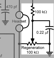
The regenerative detector circuit employs a field effect transistor (FET) as the primary active component, which is pivotal in the signal detection process. Feedback is managed through a variable capacitor, enhancing the circuit's performance akin to traditional valve designs. The inclusion of a ferrite rod is instrumental for local station reception, negating the need for an external antenna, thus simplifying the overall design.
The FET stage operates as a standalone receiver; however, the audio output levels are modest. To address this, an NPN bipolar transistor is integrated for audio amplification, ensuring that the output is sufficient for speaker use, particularly for local stations. The transformer in the collector, rated between 1k to 8 ohms, facilitates compatibility with both low and high impedance headphones, allowing for versatile audio output options.
The project aims to deliver a straightforward receiver design utilizing commonly available components, with the exception of the main tuning capacitor. A variable capacitor with a range of 10 to 415 pF is utilized, which is typically found in older valve radios and early transistor models. Although these components may be scarce in new condition, they remain accessible at hamfests. This capacitor's broad tuning range enables coverage of the AM broadcast band and 160 meters without compromising the lower frequency range.
The design process includes consideration for the physical layout of components within the enclosure. The ferrite rod's dimensions may require adjustment to fit the case, and the front panel must accommodate the vernier drive for tuning. The assembly process starts with securing larger components like the vernier drive and variable capacitors, followed by ensuring that the circuit board is mounted effectively to minimize lead lengths and maintain signal integrity.
Windings on the ferrite rod are critical for determining the frequency response and feedback characteristics of the receiver. The use of 0.4 mm diameter enamelled copper wire for all windings is recommended due to its manageability and compactness. Consistency in winding direction is essential, and insulating tape should be used to secure coil ends while maintaining a specified distance between each coil.
In summary, this regenerative detector circuit is designed for simplicity and effectiveness, leveraging readily available parts while ensuring compatibility and performance through careful consideration of component selection and layout. The construction of the receiver emphasizes the importance of maintaining short lead lengths and proper mounting techniques to optimize performance and user experience.The regenerative detector uses a field effect transistor (FET). Like with the better valve designs, feedback is controlled by a variable capacitor. A ferrite rod was used to allow reception of local stations without an external antenna. This FET stage forms a complete receiver on its own, but the audio output is quite low. The received audio is amplified by an NPN bipolar transistor. The gain of this transistor amplifier is sufficient to provide speaker reception of local stations in most areas. The 1k to 8 ohm transformer in the collector allows the set to be used with both low and high impedance headphones.
The aim of this project was to develop a simple receiver that could be built with readily obtainable parts. With the partial exception of the main tuning capacitor, this has been achieved. A 10 to 415 pF variable capacitor was used as the main tuning capacitor. These are found in valve radios and early transistor sets. They are rare new but are still common at hamfests. Their wide tuning range make it possible to cover the AM broadcast band and 160 metres without having to sacrifice coverage of the bottom end of the broadcast band.
The long shafts of these capacitors also make them easier to use with vernier dial drives. Some constructors may wish to build their set now without waiting for the next hamfest. The first version of the Moorabbin used a 60/160pF plastic tuning capacitor (same as the regeneration control) instead of the 10-415 pF unit substituted later. Receiver performance with the plastic capacitor was good. The main difficulty encountered was coupling it to the vernier dial. This was overcome by extending the shaft with a 2.5 mm diameter screw and a spacer. To compensate for the lower maximum capacitance, more turns need to be wound on to the ferrite rod to cover the whole broadcast band.
Details on this are given later. It is possible to get by without a vernier dial, but using the set will not nearly be as enjoyable, especially if you want to hear more than just the local stations. Though expensive, it is worth the cost for the benefits you get. Dick Smith P7170 is a complete reduction drive and dial, and P7172 is just the reduction drive - add your own calibrated dial for a direct frequency readout.
Ferrite rods in various lengths are available. If your ferrite rod is too long, saw a notch around it with a hacksaw. The rod is then quite brittle and can be snapped cleanly in one's hands. Obtaining these should pose no difficulty. A 2N3819 will work equally well as the MPF102 in the detector and a 2N2222 can be substituted for the BC548 in the audio amplifier. Note that the lead connections of substitute transistors may vary from those shown in Figure One. Enclosures suitable for this receiver are commercially available or can be made at home. Use a wood or plastic box so that the ferrite rod is not shielded and local stations can be received without an external antenna.
Gather all parts and plan how everything will fit together. Will the tuning capacitor fit inside the case? Does the ferrite rod need to be shortened? Is the front panel large enough to accommodate the vernier drive? How will the printed circuit board be mounted? Will internal leads be short and direct? Begin by mounting the larger parts to the case. Install the vernier drive, both variable capacitors, the switch and sockets. Figure One shows the front panel layout in the prototype. The windings on the ferrite rod determine the receiver's frequency coverage, the ability to obtain feedback so important to the set's performance and the amount of coupling between the regenerative detector and any external antenna. 0.4 mm diameter enamelled copper wire was used for all windings. This diameter is not particularly critical, but 0.4 mm is easy to work with but still results in fairly compact coils.
Wind all coils the same way around the ferrite rod. Use pieces of insulating tape to anchor the ends of each coil. Leave about 2 centimetres distance between each coil. The number of turns for each coil is shown in Figure Three. Note that if you're using a plastic variable capacitor for the main tuning capacitor you will need more turns on the main coil to cover the lower part of the band. 75 - 80 turns proved adequate in the prototype. The ferrite rod should be mounted reasonably close to both tuning capacitors and the circuit board. Try to keep leads to the coil 10cm long or less. Find or make some sort of bracket to mount the rod horizontally in the case. This bracket could use rubber grommets and plastic or be salvaged from an old transistor radio. If this is difficult to arrange, don't overlook the possibility of using a ferrite rod longer than the width of the case and drilling holes in both sides to take the rod.
🔗 External reference
Related Circuits

Frequency shift keying (FSK) is a widely used digital modulation technique for data transmission. Common applications of FSK modulation encompass both wired and wireless data transmission, as well as infrared remote controls for consumer electronic devices. FSK demodulation can...
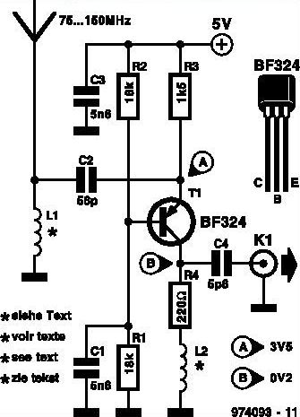
This inexpensive FM radio receiver antenna booster utilizes the BF324 TO92 style PNP transistor in a grounded-base configuration. The circuit can be employed as a... The FM radio receiver antenna booster circuit is designed to enhance the reception capabilities of...
To comprehend the interconnections between the following circuits, it is essential to first review the concept chapter. It is at the discretion of the user to select one or two of these circuits for personal development. The discussion begins...
An Icom PCR-1000 is utilized for listening to various MF, HF, and VHF radio stations. There is a minor inconvenience related to the antennas. The K9AY antenna performs well from 500 KHz to approximately 25 MHz, while the discone...
A simple radio receiver circuit is illustrated. This receiver is designed to capture signals from amateur radio stations operating in the shortwave (SW) bands of 10, 15, 20, 40, and 80 meters. The direct-conversion receiver comprises a set of...
The antenna coupling capacitor is an essential component in a regenerative receiver that does not include an RF stage, such as the Twinplex. In this type of receiver, the antenna is a vital part of the regenerative detector, and...
Warning: include(partials/cookie-banner.php): Failed to open stream: Permission denied in /var/www/html/nextgr/view-circuit.php on line 713
Warning: include(): Failed opening 'partials/cookie-banner.php' for inclusion (include_path='.:/usr/share/php') in /var/www/html/nextgr/view-circuit.php on line 713