
Infrared Transmit and Receive
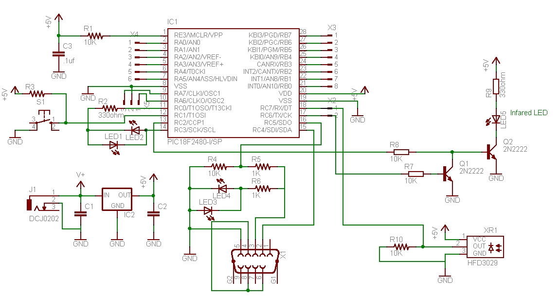
The schematic design described outlines a basic wireless communication circuit utilizing the Logochip and the Radioshack 276-640 IR Receiver Module. The Logochip serves as the primary controller, generating the necessary 38 kHz modulation signal through its internal timer. The modulation of this signal is achieved via the serial UART, which facilitates the transmission of data in the form of 8-bit bytes.
In the transmission circuit, the first transistor is responsible for driving the IR LED, receiving the square wave output from PORTC bit 2. The second transistor acts as a switch, controlling the LED's operation based on the signal from the transmit pin (TX) at PORTC bit 6. This configuration allows for efficient modulation of the IR signal, enabling the transmission of binary data.
On the receiving end, the IR Receiver Module is straightforwardly connected to a 5-volt power source, with its output linked to the RX input at PORTC bit 7. The addition of a pull-down resistor ensures stability by preventing floating states on the RX input, thus ensuring reliable data reception.
This circuit can be implemented on a breadboard for prototyping, with careful attention paid to the orientation of the IR components to maximize signal transmission and reception. This design not only demonstrates the capabilities of the Logochip in wireless communication applications but also serves as a practical example of integrating IR technology into electronic projects.When ever I find an easy way to do something I just have to make a record of it. There are some projects where you might want to do something wireless with the Logochip. This little circuit makes it pretty easy. First an explination of the Radioshack 276-640, the IR Receiver Module. It will receive signals from an IR(940nm) LED that is oscillati ng at 38killoherts. So if we want to send a series of 1 ²s and 0 ²s we modulate this 38KHz signal on and off. Fortunately the Logochip can produce the 38KHz signal and modulate it with very little effort from the software. G‚ We`re going to set up the internal timer module to produce the signal and set up the serial UART to modulate it.
So here let`s look at the schematic. This schematic shows the Logochip circuit to the left and the IR transmit and receive circuits to the right. There are two transistors involved in the in the transmit. The one that drives the LED is driven by the timer output PORTC bit 2 which is producing a 38KHz square wave.
But most of the time it is being held off by the other transistor which is being driven by the transmit pin (TX) PORTC bit 6. Now when you tell the serial port to transmit an 8 bit byte the serial data comes out of the TX pin and modulates the 38KHz signal on and off to the LED.
On the receiver side (this is really easy) the Radioshack part is simply hooked up to the 5 volt power and ground and the output signal runs right into the receiver input (RX) PORTC bit 7. I put a resistor to ground just in case the output drifts. That`s it. Here`s a picture of my bread board. IRlogoProtoBoard G‚. The transmit LED and the receiver module are pointing straight up and I just help my hand above it to reflect the signal back.
I can`t wait to use it in something. 🔗 External reference
Related Circuits
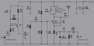
The following is a series of simple TV transmitters utilizing negative sound modulation and PAL video modulation. This design is suitable for countries employing TV systems B and G. Inductor L1 can be constructed using 24 SWG wire, consisting...

This circuit utilizes a 741 audio amplifier, which is connected to an amplified microphone, an FM modulator, and a CMOS timer functioning as a voltage-controlled oscillator (VCO). The timer output drives an LED, which is pulsed to produce an...
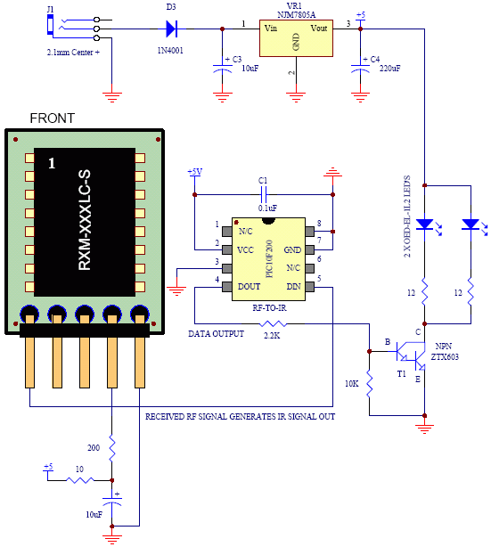
Instructions for utilizing an existing infrared transmitter from any room within the house. The concept is straightforward and operates more effectively than anticipated. This project proves to be quite useful, allowing control over devices from virtually anywhere. For instance,...

For a fixed frequency transmitter, a common method is to use a resonant quartz crystal in a crystal oscillator to establish the frequency. In transmitters where the frequency must be variable, several options are available. It is often the...
Connect a PIC microcontroller to an RN-41 Bluetooth module. The PCB was not designed by the current user, so the rationale behind the circuit's design, which differs from the voltage divider method used by others, is unclear. The 5V...
The circuit described is a 555 ultrasonic transmitter constructed to emit ultrasonic signals at a frequency of 40 kHz. It operates by generating oscillating pulse outputs from a 555 timer (specifically the T-40-16 model). The circuit is designed to...