
Transmit Infrared Signals Through Walls
The project involves two primary circuits: the infrared to RF circuit and the RF to infrared circuit. The first circuit captures infrared signals using the TSOP-1140 detector, which is sensitive to 40kHz modulated signals. This signal is then inverted using a PNP transistor before being sent to the TXLC-315 RF transmitter, which transmits the modulated signal over RF frequencies. The RF receiver circuit, comprising the RXLC-315 module, captures the transmitted RF signals and feeds them into the RF-to-IR IC, which demodulates the RF signal back into an infrared format, allowing control of IR devices remotely.
For practical implementation, the components required include the TSOP-1140 IR detector, TXLC-315 RF transmitter, RXLC-315 RF receiver, and the PIC10F200 microcontroller. The design must take into account the power supply requirements for each module, ensuring that adequate voltage and current levels are maintained for reliable operation. The PNP transistor inverter circuit must be configured correctly to prevent unintended activation of the RF transmitter. Additionally, careful attention should be paid to the layout of the circuit to minimize interference and ensure stable operation, particularly in environments with multiple electronic devices.
By following the outlined procedures and utilizing the specified components, users can successfully create a system that allows for seamless control of infrared devices from any location within the house, enhancing convenience and functionality in home entertainment systems.How to use your existing infrared transmitter from any room in the house. The principal is really pretty simple, and it works better than you would think. This is a "very handy" little project. With this gadget you can control anything from pretty much anywhere. Even place your stereo equipment inside an enclosure then use your existing IR remote control without line of sight. Adjust the volume on your stereo from other rooms in the house. You name it - so enjoy. ;o] I have tested both circuits with TV`s, stereo`s, and various VCR`s & CD players. I can change channels, adjust volume, etc, from any room in the house (and outside) where I have the IR to RF circuit in Figure #1. The RF to IR circuit in Figure #2 is placed on a bookshelf across our living room, and aimed in the direction of our TV & stereo.
Note: You can place the IRLED on long wires to extend it right onto the front of the equipment you need to control and do away with the Zetex 603 High-Current IRLED drive circuit. I`m a little power hungry, and always like to see just how far I can push the envelope, but you may prefer to tone this down a bit.
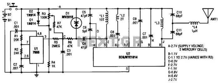
You can directly drive the IRLED with a single series resistor on the 40kHz modulating PIC for much shorter range operation. We`ll use our existing infrared remote control transmitter for our TV. We`ll transmit to the IR detector shown in Figure #1 below. The IR signal from our transmitter is output on the TSOP-1140 40kHz IR detector module data output pin (labeled RX DOUT) in Figure #1.
The IR detectors output signal feeds data to the input of the TXLC-315 RF transmitter module through the 2N3906 PNP transistor inverter circuit. When no data is being received from the IR transmitter, the PNP transistor & TXLC-315 RF module are both OFF.
We need this inverter circuit since the TXLC-315 data input needs to be held at ground during idle (non-transmit) periods. The output of the TSOP-1140 IR detector idles at logic 1. Applying this logic 1 directly to the TXLC-315 data input would cause the TXLC-315 RF transmitter to always be ON.
We don`t want this. We only want incoming data from the IR transmitter to turn ON the RF transmitter to re-create the same signal the IR transmitter is sending. That`s the purpose of the PNP inverter circuit. In essence, we`re simply turning IR into RF since the IR detector output will now modulate our RF module thereby re-creating the same signal, but now it`s RF instead of infrared.
We use our IR transmitter to send data from any room in the house by installing the circuit shown below in Figure #1 on our TV IR transmitter, or building one of the circuits shown in Figure #1 for each room. Now all we need is the circuit that receives the RF signal, then re-creates this same data signal in infrared.
The circuit shown below in Figure #2 does exactly what we need. Note: We`ve revised the RXLC-315 circuit boards. These are now 5-pin VS the old 4-pin boards. We`ve included a link to the older version board (and old version RF-TO-IR IC) for this project below. Anyone using the newer 5-pin modules & PIC10F200 RF-TO-IR IC, refer to Figure #2. The RXLC-315 RF receiver module receives the incoming RF transmission from the TXLC-315 transmitter. The RXLC-315 outputs this incoming data stream to the DIN pin of the 8-pin IC labeled RF-TO-IR shown above in Figure #2.
The 8-pin IC is a custom programmed PIC10F200 that samples the data input pin labeled DIN, then re-creates this same data signal modulated at 40Khz. Presto. We now have turned our incoming data back into a modulated IR signal, and we now have a standard TV or other appliance IR transmitter we can use anywhere in the house with our existing stereo, TV, CD players, etc, etc.
To assemble the code below you`ll need the Microchip MPASM assembler, a PIC programmer, and, of course, a PIC10F2 🔗 External reference
Related Circuits
This transmitter can be utilized for multiple applications. An INS8048L microprocessor produces various codes based on keypad inputs. These codes are modulated onto a 40-kHz carrier frequency. Additionally, Q1 drives infrared LEDs LED1 and LED2. The transmitter circuit primarily consists...
The transmitter provides an optical link (infrared) for headphones. Three infrared LEDs (IR) are powered by T1, with P1 used to adjust the current level. The current consumption of this headphones infrared transmitter is approximately 60mA at 9V. The infrared...
Two circuits for laser transmitters are described. The first circuit utilizes a simple laser pointer module, with 3 or 5mW devices functioning effectively. Higher power units are often imported from the USA or Hong Kong compared to UK approved...
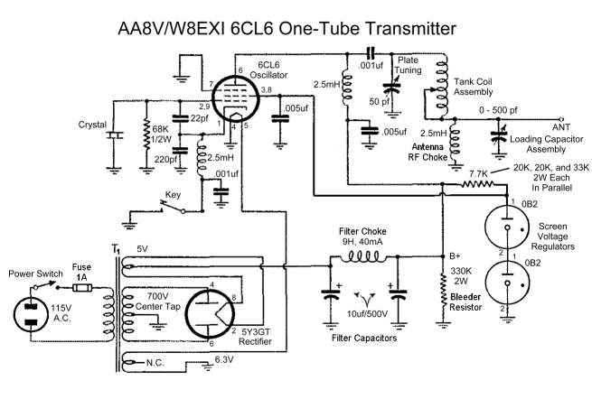
A8V W8EXI 6CL6 One Tube Transmitter. The operation of the 6CL6 transmitter is actually quite sophisticated. The A8V W8EXI 6CL6 One Tube Transmitter is a compact and efficient radio frequency (RF) transmitter that utilizes a single 6CL6 vacuum tube for...
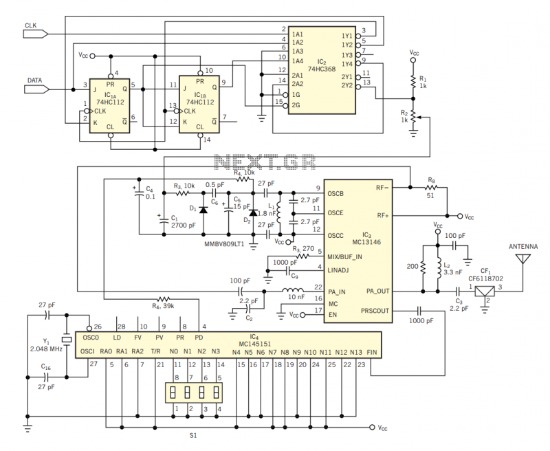
The circuit in Figure 2 shows a 16-channel, AMI-encoded RF transmitter for data rates as high as 28.8 kbps. The circuit operates in the unlicensed (FCC Part 15) 902- to 928-MHz industrial, scientific, and medical (ISM) band and is...

This stereo FM modulator circuit utilizes the BH1417F FM stereo transmitter IC, which includes a stereo modulator for generating stereo composite signals and an FM transmitter for broadcasting an FM signal wirelessly. The stereo modulator produces a composite signal...