
Intelligent trailing switch
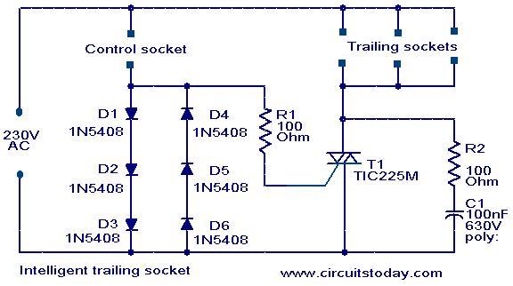
This circuit utilizes a control mechanism based on a triac, which is a semiconductor device capable of controlling power. The control socket is designed to manage the operation of the trailing sockets, ensuring that the latter only receive power when the former is active. The diodes in the circuit serve as rectifiers, allowing current to flow in one direction while blocking it in the opposite direction, thus creating a voltage drop that is essential for triggering the triac.
The snubber circuit, composed of resistor R2 and capacitor C1, is crucial for protecting the triac from voltage spikes that may occur due to inductive loads, such as motors. This protection is vital to enhance the reliability and longevity of the triac, preventing premature failure due to transient voltage conditions.
The design is versatile, accommodating a range of devices, but caution must be exercised when connecting modern electronics. Many contemporary appliances do not fully disconnect from the power supply when turned off, which can inadvertently cause the triac to remain activated due to the minimal current draw in standby mode. This characteristic can lead to unintended operation of devices connected to the trailing sockets, highlighting the importance of understanding the specifications of connected equipment to ensure proper functionality of the circuit.This is a very simple yet effective circuit in which the equipments connected at the so called trailing sockets will run only if the equipment connected at the control socket is switched on. For example, let`s connect a motor is connected to the control socket and a lamp is connected at the trailing socket.
The lamp will glow only when the motor i s running. When the load connected at the control circuit is switched on, the load current flows through the diodes and as a result there will a voltage drop across the diodes. This voltage drop is sufficient enough to switch on the sensitive triac T1 and the equipments connected at the trailing sockets gets power supply.
The components R2 and C1 forms a snubber circuit which protects the triac from transient fluctuations. Almost all equipments like motors, drills, blenders, fan, old TV, radio, amplifiers etc can be connected at the control socket.
In case of modern TV, computers, amplifiers, etc the power switch does not completely isolate the equipment and the equipment will draw a small amount of current in the standby mode which is sufficient enough to trigger the triac. Such equipments cannot be used on the control socket because it makes the trailing equipments ON even if the control equipment is OFF.
🔗 External reference
Related Circuits
This schematic represents a simple water or liquid level sensor relay switch circuit, designed to control electronic appliances based on water levels. The circuit is particularly useful for automatically turning off a water pump when a water tank, pool,...
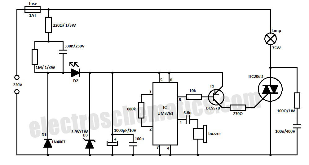
This whistle light switch allows for the control of lighting installations. The primary component of this circuit is the UM3763 integrated circuit, manufactured by UMC. A piezo-ceramic buzzer serves as a microphone, detecting sound frequencies between 1.2 kHz and...
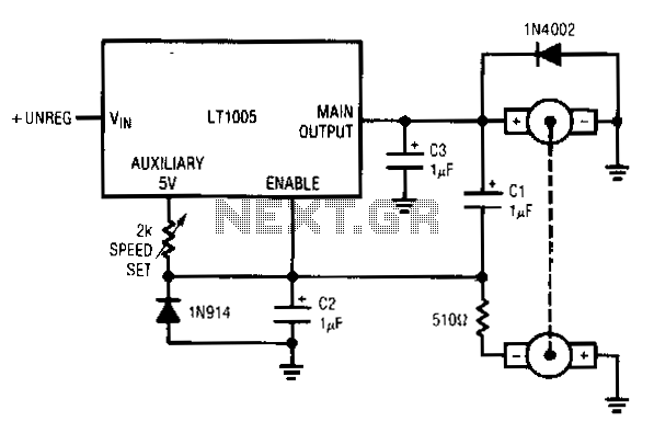
This circuit utilizes a tachometer to generate a feedback signal that is compared to a reference provided by the auxiliary output. Upon power application, the tachometer output is initially zero, allowing the regulator output to activate and supply current...
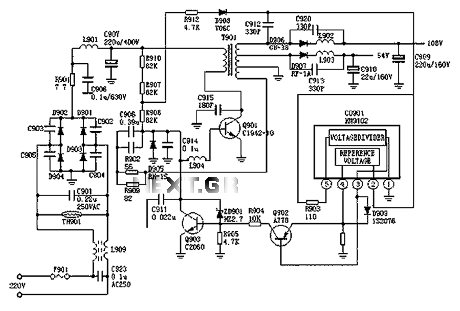
The Hitachi NP8C switching power supply circuit is illustrated in FIG. The Hitachi NP8C power models include CTP236, CEP320D, CRP350D, 450D, Furi HFC-236, 450, and Venus C37-401, C46-1, C563, among others. This circuit was widely used in early Chinese...
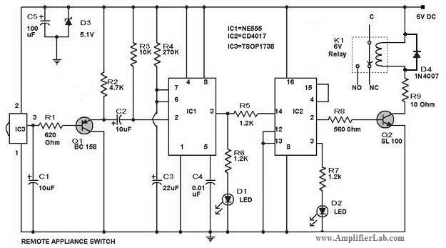
The circuit diagram of a remote-controlled appliance switch circuit includes two main components: IC1 (NE 555) and IC2 (CD 4017). The remote-controlled appliance switch circuit is designed to allow users to control electrical appliances wirelessly. The heart of this circuit...
A relay is controlled by a closed circuit in a digital logic setup, utilizing a touch input switching circuit. The described circuit involves a relay that operates based on a closed circuit condition within a digital logic framework. The relay...