
Intercom circuit with LM380

The described circuit serves as a basic intercom system facilitating communication between two individuals. It utilizes a single transistor (Q1) configured as a common base amplifier, which is effective for low impedance applications. In this configuration, the input signal from the speaker is fed into the emitter of Q1. The low impedance of the speaker is matched with the input impedance of the amplifier, ensuring optimal signal transfer and amplification.
When one individual presses their respective push-button, the circuit activates Q1, which amplifies the weak audio signal generated by the speaker. This amplified signal is then routed to an audio power amplifier IC, specifically the LM380. The LM380 is designed to drive speakers and can output significant power, making it suitable for this application. It is capable of delivering around 14 watts of output power, which is sufficient for clear audio reproduction in typical intercom scenarios.
The circuit can be assembled on a vero board, which provides a straightforward prototyping solution. However, for enhanced performance and reliability, designing a printed circuit board (PCB) is recommended. A PCB allows for better signal integrity, reduced noise, and a more compact design, which is beneficial for maintaining a neat installation.
In terms of components, the circuit will require the following: a low impedance speaker, a suitable transistor (Q1), the LM380 audio amplifier IC, resistors for biasing and stability, capacitors for coupling and decoupling, and push-button switches for user interaction. Proper power supply decoupling and layout considerations are critical to ensure the circuit operates effectively without unwanted interference or oscillations.Very simple and useful circuit for communication between two person. The Q1 is used to amplify the weak output signal of speaker when one push his (her) side push-button to speak. The base-common configuration of the Q1 pre-amplifier is for matching low impedance speaker with input impedance of the pre-amplifier, then it can amplify the output speaker signal well.
To drive the speaker, the circuit use an audio power amplifier IC, LM380. The circuit can be build on a vero board to obtain a good result, but if you use a PCB, it will work better and using of it will be easier. 🔗 External reference
Related Circuits
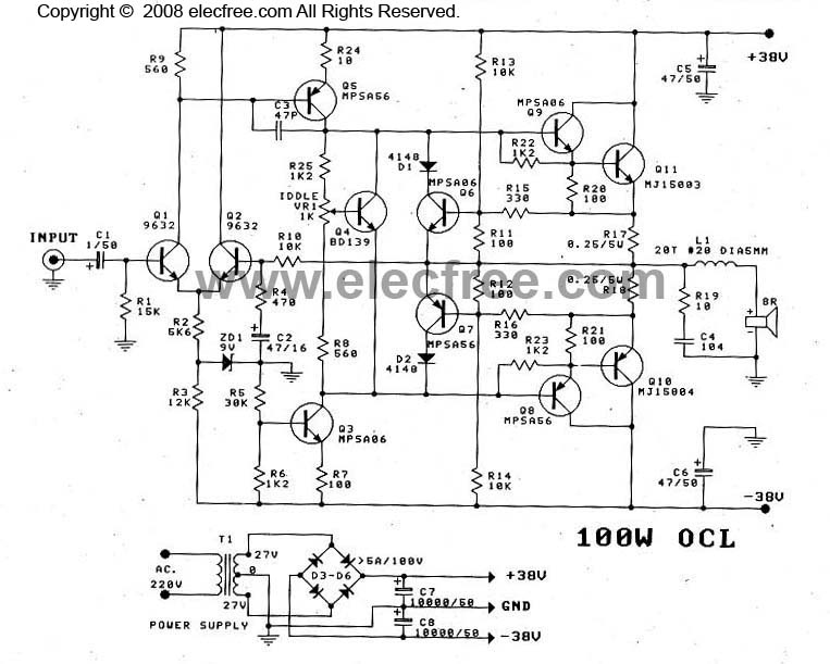
This OCL 100W power amplifier offers excellent sound quality. The circuit features direct coupling throughout to minimize low-frequency cut-off issues, enhancing super bass performance. The input signal for the tone controls enters via capacitor C1 to the base pin...
3V battery-powered circuit that emits a beep after a fixed delay of several minutes. This circuit was created in response to requests from users seeking a timer functionality. The described circuit operates on a 3V power supply, making it suitable...
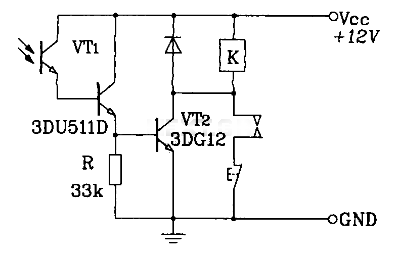
A Darlington phototransistor serves as the primary component for the photoelectric function within a self-locking control relay circuit. The circuit utilizes a Darlington phototransistor, which is known for its high current gain and sensitivity to light. This device is configured...
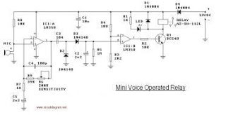
This circuit diagram represents a voice-operated relay. It functions similarly to a sound-activated switch circuit, which activates or deactivates the switch based on sound input. The output switch of this circuit operates through a relay. The voice-operated relay circuit typically...
The following file contains detailed information about the design of a basic clock oscillator circuit diagram. Included in this file is information about selecting the components. The clock oscillator circuit is a fundamental component in various electronic systems, providing a...

This circuit is designed to provide automatic current limiting up to 8.4 A. Unlike traditional current limiters that rely solely on a resistor, this circuit minimizes voltage drop until a specified current threshold is exceeded. The current limit can...