
interfacing 7seg with avr slicker

The seven-segment display is widely utilized in various electronic applications due to its simplicity and effectiveness in displaying numerical information. In typical configurations, the segments are labeled from 'a' to 'g', with an optional dot segment for decimal representation. The arrangement allows for the illumination of specific segments to form the desired numeral.
For interfacing with an AVR microcontroller, each segment of the display is connected to a designated output pin on the microcontroller. The common cathode configuration connects the cathodes of the LEDs to ground, while the anodes are driven high by the microcontroller to turn on the respective segments. Conversely, in the common anode configuration, the anodes are connected to a positive voltage, and the segments are turned on by grounding the corresponding pins.
The AVR microcontroller can be programmed to control the display through a simple routine that sends the appropriate signals to the display pins for the desired numeral. The use of multiplexing techniques can also enhance the efficiency of displaying multiple digits. In multiplexing, only one digit is activated at a time, rapidly switching between them to create the illusion of simultaneous illumination.
In a practical application, power supply considerations are crucial. A stable +12V supply is recommended for the AVR Slicker Board, ensuring that the microcontroller and the display operate within their specified voltage ranges. Proper decoupling capacitors should be employed near the power pins of the microcontroller to mitigate noise and ensure reliable operation.
Debugging the connections and code is essential in troubleshooting any issues with the display. The use of a logic analyzer or oscilloscope can help verify that the correct signals are being sent to the display. Additionally, testing each segment individually can confirm that the display itself is functioning correctly.
Overall, the integration of a seven-segment display with an AVR microcontroller represents a fundamental aspect of digital electronics, providing a clear and effective means of displaying numerical data in various applications.A seven segment display is the most basic electronic display device that can display digits from 0-9. The most common configuration has an array of eight LEDs arranged in a special pattern to display these digits.
They are laid out as a squared-off figure 8`. Fig. 1 shows how to interface the seven segments with microcontroller. A seven segment is generally available in ten pin package. While eight pins correspond to the eight LEDs, the remaining two pins (at middle) are common and internally shorted. These segments come in two configurations, namely, Common cathode (CC) and Common anode (CA). We now want to display a four digit number in AVR Slicker Board by using seven segment displays. The seven segment display is connected with ARV microcontroller. To compile the above C code you need the CodeVision AVR software. The software has it`s own IDE and built-in AVR gcc- Compiler. They must be properly installed and a project with correct settings must be created in order to compile the code.
To compile the above code, the C file must be added to the project. In CodeVision AVR software, you can develop or debug the project without any hardware setup. You must compile the code for generating HEX file. In debugging Mode, you want to check the port output without microcontroller Board. Give +12V power supply to AVR Slicker Board; the four seven segment display is connected with the AVR Slicker Board. First check the entire seven segments LED`s are properly working or not. Here we are display just 1234 in four seven segment. The entire seven segments receive it through Port lines & display it in order. If any data is not coming in seven segments, then you just check the entire seven segments LED`s are working or not.
Change the seven segment driver IC & Check the I2C connections. Check the four seven segments connections. Otherwise you just check the code with debugging mode in CodeVisionAVR. 🔗 External reference
Related Circuits
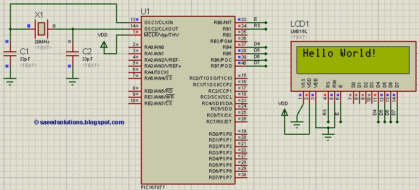
This tutorial on the PIC16F877 microcontroller addresses the question, "How to interface an LCD in 4-bit mode with the PIC16F877?" It also utilizes the PIC16 simulator (Proteus). The PIC16F877 microcontroller is a versatile device widely used in embedded systems. This...

Usually we see Digital clock on LCD or 7 segment. But, this AVR Digital Clock which is designed by Ficara Emilio displayed on Oscilloscope. The project uses ATtiny 2313 as the main controller. What an interesting microcontroller project. Source...
The IR3721 is a versatile power or current monitoring integrated circuit (IC) designed for low-voltage DC-DC converters. It monitors the inductor current in buck or multiphase converters by utilizing either a current sensing resistor or the inductor's winding resistance...
The parallel interface transfers data in 8 bits (or more) simultaneously, utilizing eight separate wires. It serves as an extension of the data bus to external devices. This interface is particularly suitable for devices that operate in binary states,...
Ethernet has traditionally been a complex interface. All Ethernet chips up until now have had 100 pins or more, making them difficult to find in small quantities and challenging to use with microcontrollers that have limited memory. Microchip has...
This simple AVR programmer is capable of transferring hex programs to most ATMEL AVR microcontrollers. It is more reliable than many other simple AVR programmers available and can be constructed in a very short amount of time. This programmer...