
interfacing arduino with a telit gm862
The provided code snippet demonstrates the implementation of the GM862-GPS module with an Arduino Mega. The sketch initializes the modem, switches it on, and checks for network registration before proceeding with GPRS setup. The modem's functionalities include sending HTTP requests, receiving responses, and sending SMS messages. The setup function ensures that the modem is powered and ready for communication, while the loop function listens for user commands to perform various actions, such as switching off the modem, sending SMS messages, and requesting GPS data.
The Arduino Mega is connected to the GM862-GPS module via Serial3, allowing for communication through defined commands. The modem's on/off control is managed through a designated pin, and a character array stores the user-defined PIN for GPRS access. The code includes functions for network registration, GPRS context initialization, and socket management for HTTP requests. The implementation of a timeout mechanism during data reception ensures that the system attempts to read data for a specified duration. The GPS functionality is also integrated, allowing for real-time location tracking and output of latitude, longitude, and altitude data.
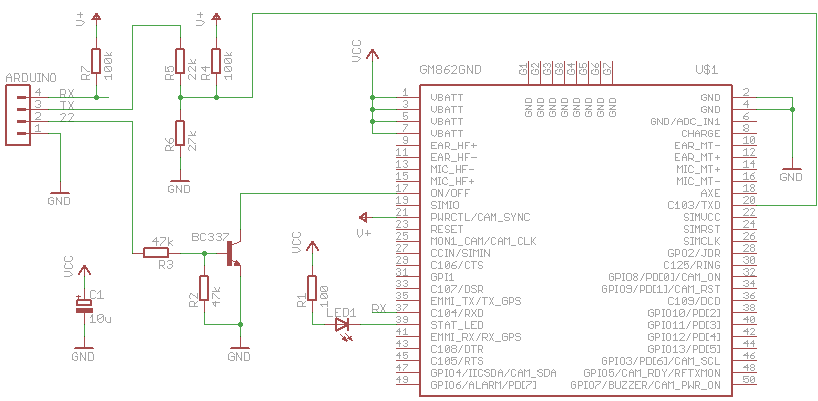
In summary, this Arduino-GM862 integration provides a versatile platform for mobile communication and GPS tracking, enabling various applications in remote monitoring and data transmission. The careful consideration of power supply requirements and communication protocols enhances the reliability and functionality of the system.The Arduino can talk over a wide range of networks. Ethernet, Bluetooth, Wifi, XBEE and GPRS to name the most known. I had a Telit GM862-GPS module laying around, unused for some time already. It has GPRS and GPS capabilities, both accessible with AT commands. So I decided to port some of my code to the Arduino. The logic pins of the GM862 accept only CMOS 2. 8 Volt. For that reason, a voltage divider is needed for the Tx line. Both, Rx and Tx are pulled up to the PWR_CTL line of the module because these pins don`t have an internal pull up resistor. The bad thing for this setup is the power supply. The module is powered by a LiPo cell (3. 7 V with 2000 mAh). The Arduino Mega is powered by the USB port. If I want to make this portable, I have to use two batteries. Or find a better solution. Maybe powering the Arduino with a step-up converter. First I wanted to use an Arduino Pro mini, that runs on 3. 3 V. That would save me from having two different power supplies for the Arduino and the GM862. I tried to connect the Rx/Tx lines to two digital pins and use the NewSoftSerial library. This library enables a second serial port on the Arduino besides the hardware serial port. Unfortunately it wasn`t reliable enough. Sending to the module seems to work well, receiving sometimes did not. I tried it with different baud rates and different Arduinos, 8 MHz and 16 MHz, but that didn`t help. Maybe I did something wrong, but I couldn`t figure it out. Nevertheless, here is a small snippet, that shows features that are already working. To get it working, you have to replace XXXX with your PIN. For GPRS you have to dig into the module code and adapt the GPRS settings. /* * GM862-GPS testing sketch * used with Arduino Mega * */ #include "GM862. h" int onPin = 22; // pin to toggle the modem`s on/off char PIN[5] = "XXXX"; // replace this with your PIN Position position; // stores the GPS position GM862 modem(&Serial3, onPin, PIN); // modem is connected to Serial3 char cmd; // command read from terminal void setup() { delay(10000); Serial.
begin(19200); Serial. println("GM862 monitor"); modem. switchOn(); // switch the modem on delay(4000); // wait for the modem to boot modem. init(); // initialize the GM862 modem. version(); // request modem version info while (!modem. isRegistered() { delay(1000); modem. checkNetwork(); // check the network availability } Serial. println("-"); Serial. println("ready"); } void request { char buf[100]; byte i = 0; modem. initGPRS(); // setup of GPRS context modem. enableGPRS(); // switch GPRS on modem. open // open a socket Serial. println("sending request. "); modem. send("GET /search. atom q=gm862 // search twitter for gm862 modem. send("HOST: search. twitter. com port "); // write on the socket modem. send(" "); Serial. println("receiving. "); while (i+ < 10) { // try to read for 10s modem. receive(buf); // read from the socket, timeout 1s if (strlen(buf) > 0) { // we received something Serial. print("buf:"); Serial. println(buf); i-; // reset the timeout } } Serial. println("done"); modem. disableGPRS(); // switch GPRS off } void loop() { if (Serial. available() { cmd = Serial. read(); switch (cmd) { case `o`: modem. switchOff(); // switch the modem off break; case `s`: // send a SMS. Replace with your number modem. sendSMS("6245", "your@email. com hello from arduino"); break; case `w`: modem. warmStartGPS(); // issue a GPS warmstart break; case `p`: position = modem. requestGPS(); // request a GPS position if (position. fix = 0) { // GPS position is not fixed Serial. println("no fix"); } else { // print lat, lon, alt Serial. print("GPS position: "); Serial. print(position. lat_deg); Serial. print(". "); Serial. print(position. lat_min); Serial. print(", "); Serial. print(position. lon_deg); Serial. print(". "); Serial. print(position. lon_min); Serial. print(", "); Serial. println(position. alt); } break; case `h`: request // do a sample H 🔗 External reference
Related Circuits
DAC stands for Digital to Analog Converter. This article explores the code created by Michael Smith for a PWM-based DAC. The code has been modified to allow for the testing of various DAC options. A comparison is made between...
A straightforward project involves using an Arduino to rotate a GH-2 camera on a fluid head by specified degrees to capture 360-degree panoramas. The motor control is uncomplicated, and there is a wealth of DIY motor projects available. Assistance...
Software on a MacBook Pro includes Laidman & Katsura's WaveWindow, which functions as a software oscilloscope. It is beneficial for individuals working with sound on the Mac, offering an educational and entertaining experience. Additionally, Faberacoustical's Signal Scope allows for...
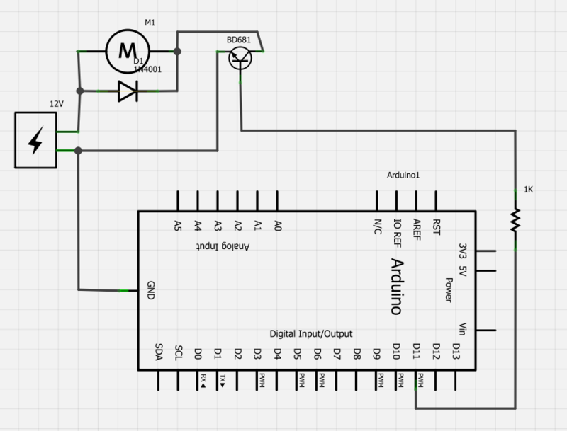
Power a 12V fan using a Darlington transistor to control the speed from an Arduino. When wired as described, nothing happens even though a PWM signal is being sent. It is suggested to edit the question and ensure the...
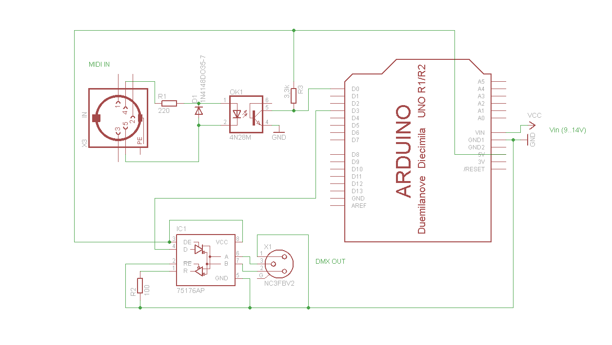
A simple Arduino MIDI-to-DMX control was created for a robot band named Science Fiction Children. The setup consists of two inexpensive LED Par56 lights from Stairville, a basic DMX dimmer pack, and Ableton Live for sound management. The objective...
The Raspberry Pi single-board computer (SBC) has garnered significant attention for being a complete system priced under $50. However, it is not the most affordable computing device available. For only $13.50, a mini computer that connects to a PC's...