
midi to dmx arduino control shield

The Arduino sketch initializes the system by setting up the necessary pin modes and configuring the DMX output. The main loop continuously checks for incoming MIDI data, interpreting note on/off messages and executing corresponding actions. If a note on message is received, the note value is stored, and further incoming data is processed to determine the velocity, which sets the brightness for the respective DMX channel. The playNote function translates the MIDI note and velocity into DMX values, allowing for control of the RGB channels of the LED lights.
The DMX channel configuration is as follows: for device 1, channel 1 sets the DMX mode, channel 2 controls red (MIDI note 1), channel 3 controls green (MIDI note 2), and channel 4 controls blue (MIDI note 3). Device 2 follows a similar structure with its channels starting from channel 8. This setup provides a flexible and efficient method for integrating MIDI control into lighting systems for live performances.I hacked together a quick and dirty Arduino MIDI-to-DMX control for our robot band Science Fiction Children. It`s really simple! And here`s how I did it. I have two really cheap LED Par56 from Stairville (DMX controlled), a simple DMX-Dimmer pack and use Ableton Live for our sound setup.
So all I want is to control the differentcolors and dimmer channels (DMX channels) with each one Midi-Note. The pitch (note) shall represent the channel, the midi velocity shall represent the actual DMX-value (brightness). Some words about the DMX protocol: This is a really simple serial protocol, the connectors are 3-pole XLR and yep you can use normal audio XLR-cables.
The devices (my LED-Par for example) are connected in a chain. Each device can have one or more channels, there are up to 255 channels per chain possible. Let`s have a look at a standard LED PAR56 channel setup: So all we have to do is to send something from 0 to 63 to channel 1 to set the device to RGB Mode and then the brightness value (0. 255) to channel 1. 3 for the brightness of the different colors. Really easy. When you set another start address for the DMX Device, the 5 channels are shifted, e. g. to 7, 8, 9, 10, 11. You have two sections: opto copler 4N28 for handling the MIDI-In. You can probably use other types like the 4N38 as well. Secondly the DMX output section that consists of a serial converter 75176, here you could also use the standard chip MAX481 (see this tutorial ) // welcome to MIDI to DMX by moritz Simon geist.
// Ressources, setup and hardware: // DmxSimple is available from: // Help and support: */ #include
You can * easily change the number of channels sent here. If you don`t * do this, DmxSimple will set the maximum channel number to the * highest channel you DmxSimple. write() to. */ DmxSimple. maxChannel(5); } void loop () { if (Serial. available() > 0) { // read the incoming byte: incomingByte = Serial. read(); // wait for as status-byte, channel 1, note on or off if (incomingByte= 144){ // note on message starting starting action=1; }else if (incomingByte= 128){ // note off message starting action=0; }else if (incomingByte= 208){ // aftertouch message starting //not implemented yet }else if (incomingByte= 160){ // polypressure message starting //not implemented yet }else if ( (action=0)&&(note=0) ){ // if we received a "note off", we wait for which note (databyte) note=incomingByte; playNote(note, 0); note=0; velocity=0; action=2; }else if ( (action=1)&&(note=0) ){ // if we received a "note on", we wait for the note (databyte) note=incomingByte; }else if ( (action=1)&&(note!=0) ){ //.
and then the velocity velocity=incomingByte; playNote(note, velocity); note=0; velocity=0; action=0; }else{ //nada } } } void playNote(byte note, byte velocity){ int value=0; if (velocity >10){ value=255; }else{ value=0; } // =DEVICE 1= // DMX CHANEL 1: "2" for seting DMX Mode // DMX CHANEL 2: 0. 255 Control Red ->. MIDI Note "1" (possible C-2) // DMX CHANEL 3: 0. 255 Control Green ->. MIDI Note "2" // DMX CHANEL 4: 0. 255 Control Blue ->. MIDI Note "3" // DMX CHANEL 5: NADA // =DEVICE 2= // DMX CHANEL 8: "2" for seting DMX Mode // DMX CHANEL 9: 0.
255 Control Red ->. MIDI Note 4 // DMX CHANEL 10: 0. 255 Control Green ->. MIDI Note 5 // DMX CHANEL 11: 0. 255 Control Blue ->. MIDI Note 6 // DMX CHANEL 🔗 External reference
Related Circuits
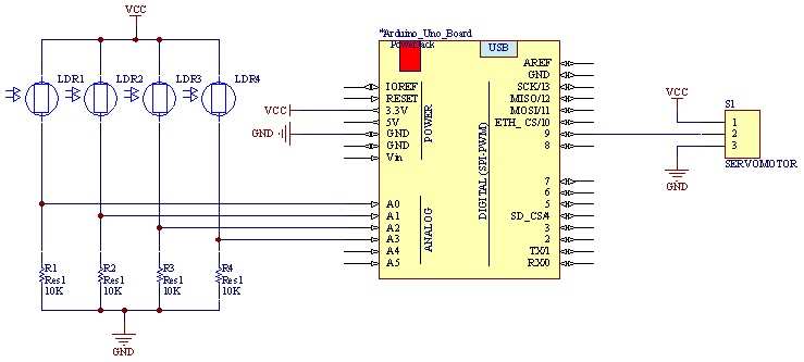
The movement of the servo is determined by the output values of the photoresistors. The impedance of these sensors changes with the amount of light incident upon them. The servo's position shifts towards the sensor that detects less light....
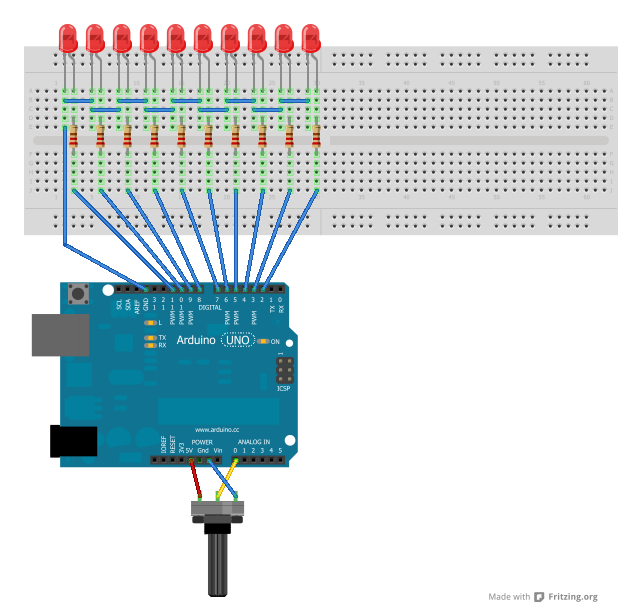
A significant amount of extra hours has been dedicated to work in anticipation of an editing deadline. Despite this, it is deemed appropriate to attempt some hardware hacking. An interest in electronics has existed since before the advent of...
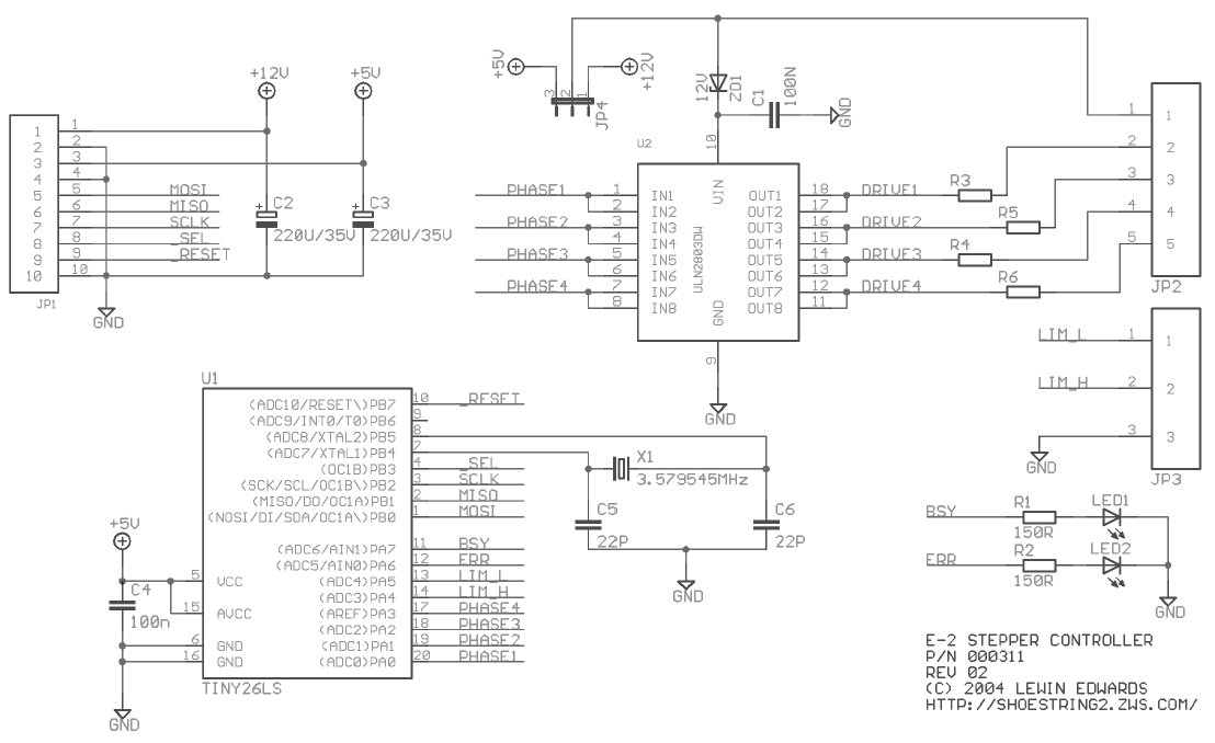
Stepper motors are beneficial for low-speed, intermediate-torque drive and positioning applications, especially where precise sub-revolution rotor position control is required. These motors are frequently utilized to drive the reels of electromechanical slot machines, position floppy disk drive heads, operate...
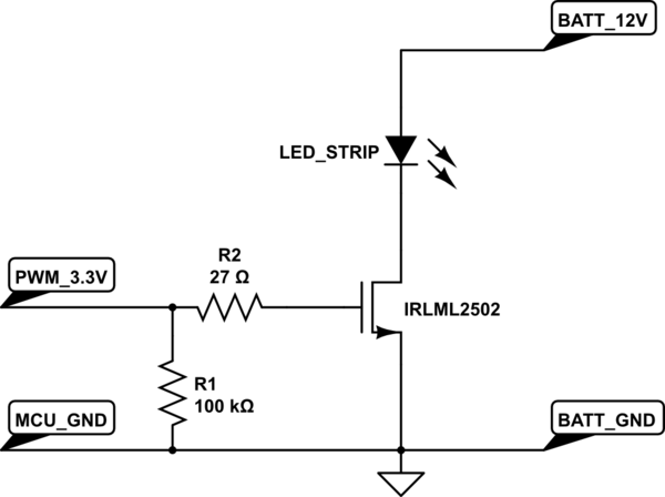
A strip of LEDs is controlled by a microcontroller using pulse-width modulation (PWM) to adjust brightness. The LED strip requires approximately 1.5A at 12V. The user, who has experience only with low-power digital electronics, seeks confirmation of their assumptions...
This digital volume control has no pot to wear out and introduces almost no noise in the circuit. Instead, the volume is controlled by pressing UP and DOWN buttons. This simple circuit would be a great touch to any...
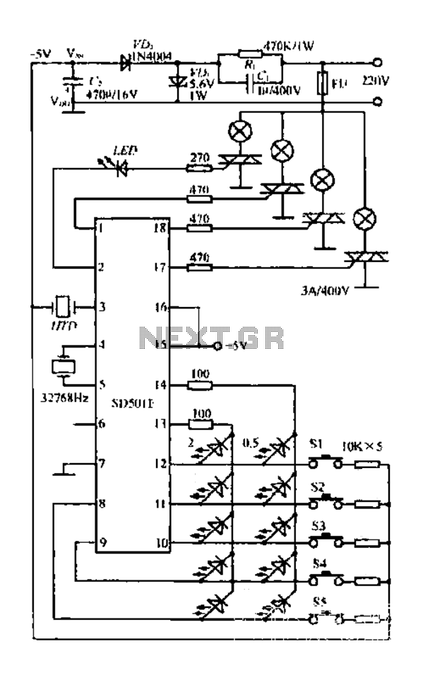
The FIG SD501E is a J tie fan integrated circuit (IC) characterized by progressive timing and three operational modes: strong, medium, and weak. It features three types of output settings and includes an electrical swing mechanism. The device is...