
Interfacing seven segment to microcontroller
The interfacing of a 7-segment display with a microcontroller involves connecting the display to the microcontroller's GPIO (General Purpose Input/Output) pins. A typical 7-segment display consists of seven individual LEDs arranged in a figure-eight pattern, plus an optional eighth segment for the decimal point. Each segment can be individually controlled to display numbers 0 through 9, as well as some letters.
To effectively control multiple 7-segment displays using the same data lines, a technique known as multiplexing or scanning is employed. In this method, only one display is activated at a time while the others remain off. By rapidly cycling through the displays, a human observer perceives all displays as being lit simultaneously due to the persistence of vision.
The first step in implementing this system is to create a lookup table that defines the binary patterns required to light up the segments for each digit. For example, to display the digit '1', the corresponding segments that need to be activated would be segments 'B' and 'C' of the display.
The microcontroller sends the appropriate binary value to the display's segments via its output pins. A common approach is to use a series of resistors to limit the current through each LED segment, preventing damage to the display. The microcontroller's firmware must include a routine to cycle through the displays, activating one at a time while updating the segment patterns according to the desired output.
In addition to the basic functionality, the design may incorporate features such as brightness control through PWM (Pulse Width Modulation), allowing for varying intensity of the segments. This can enhance visibility under different lighting conditions.
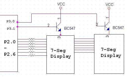
Overall, the combination of multiplexing and a lookup table provides an efficient way to manage multiple 7-segment displays with minimal pin usage on the microcontroller, enabling the display of numerical data in a clear and effective manner.The Tutorial shows how to interface 7-segment display to a microcontroller. Also explains how do display more than one 7-segment on same data lines using scanning method. 7 Seg displays are are basically 7 LED's. It will be much easier to understand if you first read Interfacing LED's to Microcontroller.
Figure 1 shows how to interface 7-seg display to a microcontroller. Now we create a lookup table containing the seven segment pattern to display the corresponding hex digits. e.g. consider we have to display '1' from the above figure we come to know tha
🔗 External referenceRelated Circuits
This simple counter can be utilized to count pulses, serving as the foundation for a customer counter, similar to those found at store entrances, or for any other counting applications. The circuit is compatible with any TTL logic signal...

In the design of microcontroller-based electronic projects, the use of a Reset IC is critical for applications that require the microcontroller (MCU) to operate only at its optimum voltage. Without reset circuitry, the MCU may enter a tristate condition,...
It is entirely feasible and acceptable to control various outputs while sitting at a PC terminal. A simple hardware circuit and software are utilized to interface with a 7-segment rolling display. The printer port of a PC provides a...
It is a single integrated circuit that includes EEPROM, RAM, an analog-to-digital converter, numerous digital input and output lines, timers, and a UART for RS-232 communication, among other features. A complete programming environment is available for Linux, allowing programming...
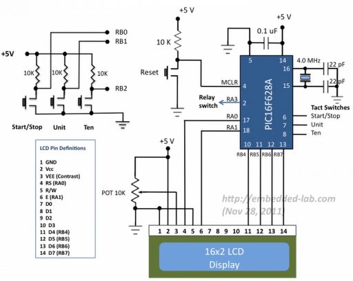
A source code for a simple PIC-based digital timer is provided. The hardware for the project is not available; however, it will be demonstrated using a DIY PIC16F628A breadboard module and I/O board. The complete circuit diagram and firmware...
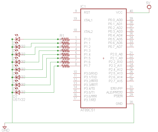
Learn how to interface LEDs with the 8051 Microcontroller. Download free source code and circuit diagram of the P89V51RD2 Microcontroller. Interfacing LEDs with the 8051 microcontroller is a fundamental project that serves as an excellent introduction to microcontroller applications. The...
Warning: include(partials/cookie-banner.php): Failed to open stream: Permission denied in /var/www/html/nextgr/view-circuit.php on line 713
Warning: include(): Failed opening 'partials/cookie-banner.php' for inclusion (include_path='.:/usr/share/php') in /var/www/html/nextgr/view-circuit.php on line 713