
LED Interfacing with 8051
Interfacing LEDs with the 8051 microcontroller is a fundamental project that serves as an excellent introduction to microcontroller applications. The P89V51RD2 microcontroller, a member of the 8051 family, is particularly suited for this task due to its versatile I/O capabilities and ease of programming.
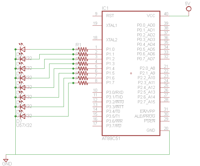
To begin, the circuit typically consists of the P89V51RD2 microcontroller connected to a series of LEDs through current-limiting resistors. Each LED is connected to a specific I/O pin of the microcontroller, allowing for individual control. The first step in the schematic design involves configuring the microcontroller pins as outputs. This can be achieved through the initialization of the appropriate registers in the microcontroller's firmware.
The circuit diagram will illustrate the connection of the microcontroller pins (for example, P0.0, P0.1, etc.) to the anodes of the LEDs, while the cathodes are connected to ground through resistors, typically in the range of 220 to 1k ohms, depending on the LED specifications and desired brightness. The choice of resistor value is crucial to ensure that the current flowing through the LEDs does not exceed their rated limits, thereby preventing damage.
The firmware should include a simple loop that turns the LEDs on and off in a sequence, which can be accomplished using delay functions to create a visually appealing effect. The source code provided may include functions for initializing the microcontroller, setting the port directions, and controlling the timing of the LED states.
In conclusion, this project not only demonstrates the basic principles of interfacing components with a microcontroller but also provides practical experience in programming and circuit design. The availability of source code and circuit diagrams facilitates a deeper understanding and enables users to replicate or modify the project for further experimentation.Learn how to interface LEDs with 8051 Microcontroller. Download free source code and circuit diagram of P89V51RD2 Microcontroller 🔗 External reference
Related Circuits
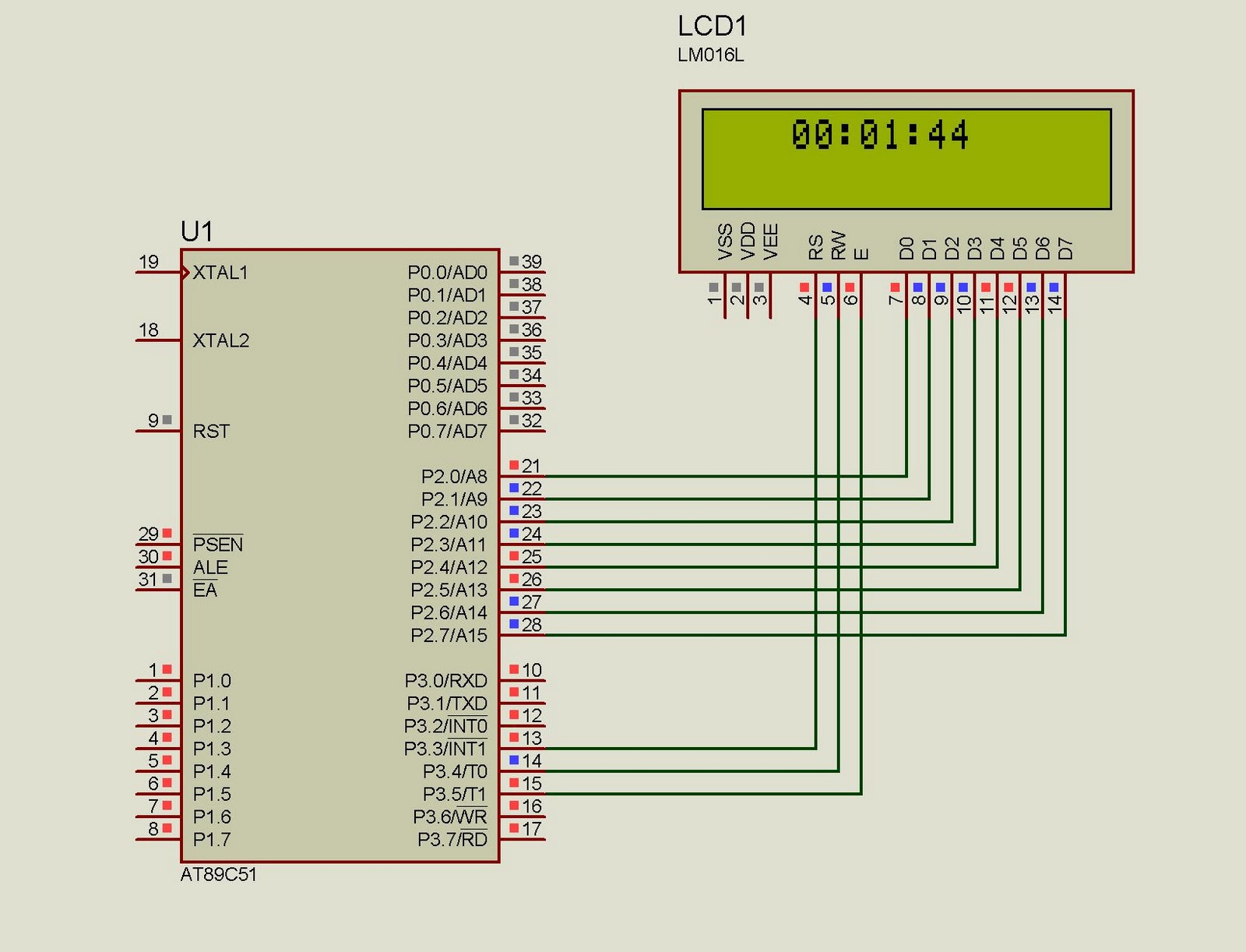
This project implements a real-time clock using the 89C51 microcontroller. The clock's data format is hours:minutes:seconds, which is displayed on a 16x2 LCD. The code has been tested and compiled using the Keil uVision compiler. The circuit diagram for...
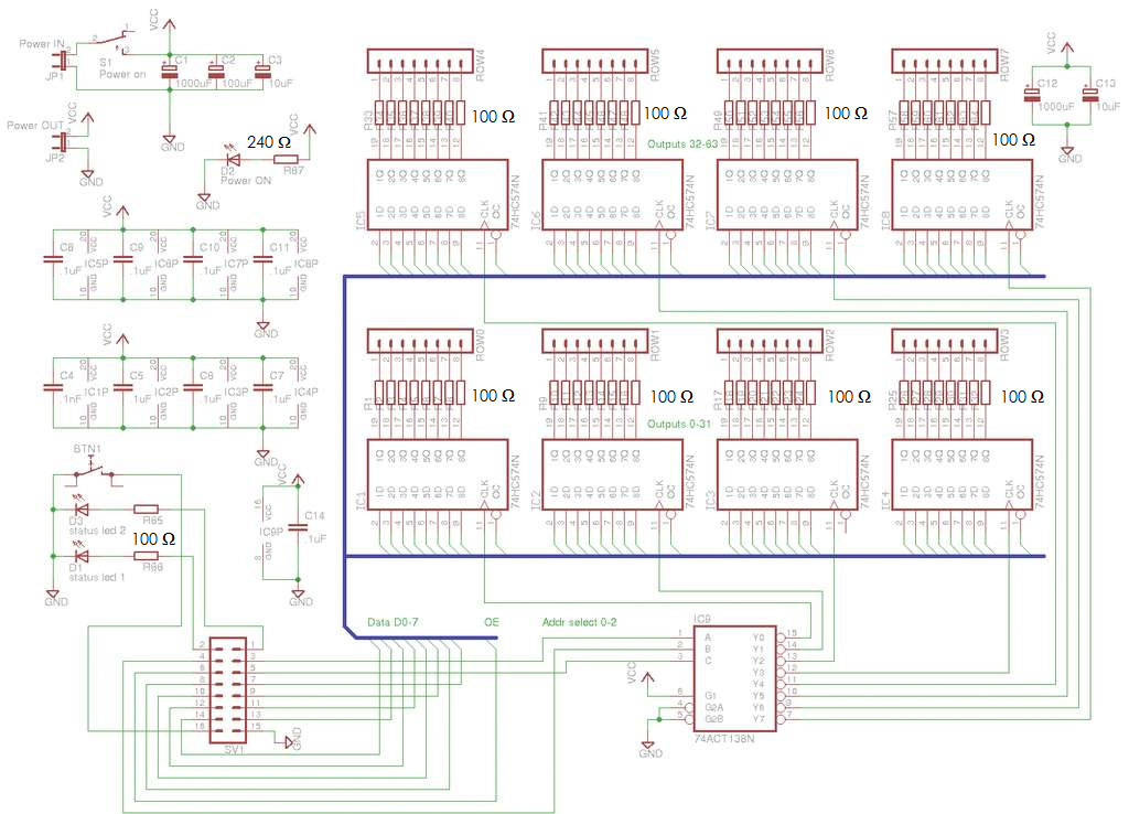
A total of 512 functional LEDs is required for the lattice assembly. These LEDs must be stable and bright. This section outlines the process for identifying faulty LEDs among the usable ones. Often, there are defective LEDs, particularly when...
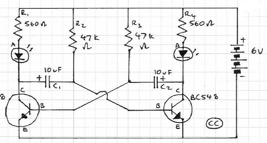
Blinks 2 LEDs in sequence. An explanation of its operation is requested. It is understood that a capacitor charges, causing the LED to turn off, and when it discharges, the LED turns on. However, clarification on the purpose of...
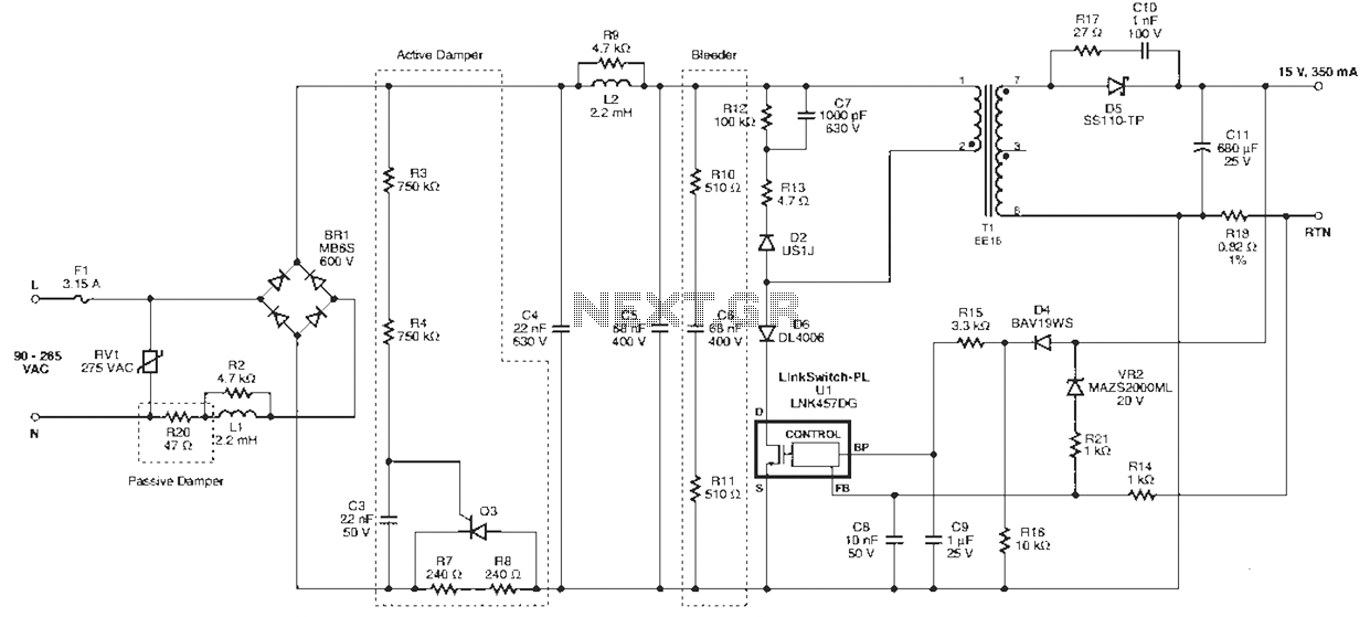
Power Integrations' DER322 reference design employs the LinkSwitch-PL family of LNK460VG devices. This design represents the industry's first alternative 100W A19 incandescent LED driver utilizing a single-layer PCB. It is characterized by low cost, minimal component count, and compact...
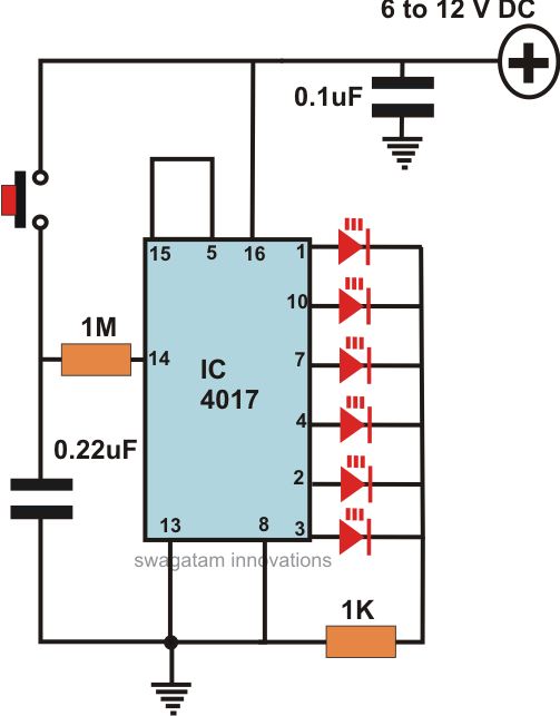
This article offers a circuit diagram and a discussion on CMOS logic and IC layout for creating a set of attention-getting LED running lights. It details a simple sequential LED flasher or light chaser that can be built, including...

This simple LED torch is powered by a 2-transistor blocking oscillator that increases the voltage from a 1.5V cell. The design utilizes the natural current limiting characteristics of a 150 µH choke to prevent the white LED from being...
Warning: include(partials/cookie-banner.php): Failed to open stream: Permission denied in /var/www/html/nextgr/view-circuit.php on line 713
Warning: include(): Failed opening 'partials/cookie-banner.php' for inclusion (include_path='.:/usr/share/php') in /var/www/html/nextgr/view-circuit.php on line 713