
Interfacing TCS3200 Colour Sensor with AVR ATmega32
The output of the TCS3200 is available on a single line, and to obtain the intensity of the red, green, blue, and clear channels, two inputs, S2 and S3, are used to select the sensor whose output is to be made available on the output line. By selecting a channel—either red, green, blue, or clear—the output pulse width can be measured to determine the intensity of that channel. The TCS3200 chip is a small SMD component, making prototyping challenging with surface mount designs. Therefore, a small module has been developed that includes the TCS3200 chip, four white LEDs, an LED control circuit, and several other basic components on a PCB. The module features connections available on a 0.1-inch male header, facilitating easy integration with microcontroller boards. The white LEDs illuminate the object placed in front of the sensor. For optimal performance, the object should be positioned approximately one inch away from the LEDs, ensuring that the beams from all four LEDs converge at a single point without creating distinct light spots on the object.
One I/O pin of the microcontroller can be utilized to switch the LEDs on and off. To measure the output frequency of the TCS3200, TIMER1 of the AVR microcontroller, which is a 16-bit timer, is employed. The time between the falling edge and the subsequent rising edge is measured. Care must be taken when the function is called if the level on the output line is already low, indicating that some time has passed since the last falling edge. The process begins by waiting for the output line to go high, at which point a falling edge is detected, and the TIMER1 counter (TCNT1) is reset to zero. The timer is then started by writing to the control register TCCR1B. The timer continues running until a rising edge is detected, at which point the timer is stopped, and a calculation is performed to determine the frequency. Finally, this frequency value is returned. A demo program illustrating the use of the TCS3200 function is provided, which operates on xBoard v2.0 and displays program output on a 16x2 LCD module. The program waits for an object to be placed in front of the sensor module.
This setup allows for an efficient and effective method of color detection, enabling various applications in fields such as robotics, automation, and interactive installations. The integration of the TCS3200 color sensor with a microcontroller provides a robust solution for real-time color analysis and object recognition, enhancing the capabilities of electronic projects.Detecting colour of an object can be an interesting and useful electronic application. It can be realized using a colour sensor like TCS3200 and a general purpose microcontroller like AVR ATmega32. TCS3200 chip is designed to detect the colour of light incident on it. It has an array of photodiode (a matrix of 8x8, so a total 64 sensors). These ph otodiodes are covered with three type of filters. Sixteen sensor have RED filter over them thus can measure only the component of red in the incident light. Like wise other sixteen have GREEN filter and sixteen have BLUE filter. As you should know that any visible colour can be broken into three primary colours. So these three type of filtered sensors helps measure the weightage of each of primary colours in incident light.
The rest 16 sensors have clear filter. TCS3200 converts the intensity of incident radiation into frequency. The output waveform is a 50% duty cycle square wave. You can use the timer of a MCU to measure period of pulse and thus get the frequency. The output of TCS3200 is available in single line. So you would ask how we get the intensity of RED, GREEN, BLUE and CLEAR channels Well it has two inputs S2 and S3 that is used to select the sensor whose output need to be made available on the out line. So we select a channel either RED, GREEN, BLUE or CLEAR and then do the measurement of the output pulse width to get that channel`s intensity.Since TCS3200 chip is a small SMD chip and is tough to prototype designs using the surface mount chip.
Thus we have made a small module that has the TCS3200 chip, four white LEDs, LED control circuit and few other basic components on a PCB. The module has the connection all the line on 0. 1inch male header. This makes it easy to connect with microcontroller boards. The white LEDs throws light on the object that is placed in front of the sensor. For best performance the object should be placed 1inch away from the LEDs such that the beam from all four LEDs converge at a single point (and do not make four distinct light spots on the object).
One i/o pin of MCU can be used to switch on and off the LED. For measuring the output frequency of the TCS3200 we have used TIMER1 of AVR. Which is 16 bit timer. We measure the time between the falling the edge and next rising edge. So we must take care when the function is called and the level on the OUT line is already LOW (that means already some time has passed from the last falling edge, so we wait for the line to become high). As soon as a falling edge is detected we start RESET the TIMER1 counter (TCNT1 to 0). Then we start the timer by writing to the control register TCCR1B. Then we wait for a rising edge. And as soon as we get a rising edge we stop the timer and do a small calculation to calculate the frequency.
Finally this frequency is returned. A demo program which shows the use of TCS3200 function is provided below. This demo program runs on xBoard v2. 0 it shows program output on a 16x2 LCD module. The program waits for an object to be placed in front of the sensor module. A 🔗 External reference
Related Circuits
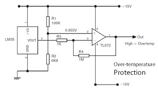
This is a basic overview of the LM35 temperature sensor, which is interfaced with an operational amplifier (op-amp) to boost its output. The LM35 provides a high output voltage when it detects high temperatures. The output can be utilized...
This is a light sensor circuit designed to detect light and activate a relay. The circuit is straightforward and requires only a few components. The operation of the circuit is simple: when the photoresistor detects light, it will turn...

The circuit utilizes a 555 integrated circuit (IC) functioning as an astable multivibrator. When a positive 9 volts is applied to pin 8, the circuit generates sound through a speaker. The connection to pin 8 is routed through a...
This circuit illustrates the NE555 timer used in a light-sensitive alarm sensor circuit diagram. Features include the ability to detect a sudden shadow falling on the sensor. The NE555 timer is a versatile integrated circuit widely utilized in various timing,...
The TRW-24G connector pins are quite small, approximately 1mm apart. To address this issue, an adaptor PCB has been ordered to convert the small connector of the RF module to a standard pin connector. The pin arrangement of the...
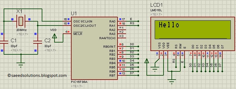
This post presents the LCD interfacing code utilizing the PIC16F84A microcontroller. The code is developed in the C programming language using MPLAB with the HI-TECH C compiler. The interfacing of an LCD (Liquid Crystal Display) with the PIC16F84A microcontroller...
Warning: include(partials/cookie-banner.php): Failed to open stream: Permission denied in /var/www/html/nextgr/view-circuit.php on line 713
Warning: include(): Failed opening 'partials/cookie-banner.php' for inclusion (include_path='.:/usr/share/php') in /var/www/html/nextgr/view-circuit.php on line 713