
Ion Chambers
The ion chamber design leverages the fundamental principles of ionization and electric field dynamics to create a sensitive radiation detection instrument. The construction begins with a cylindrical metal can, which serves as the primary housing and conductive surface for the ionization process. The central wire electrode, insulated from the can's walls, acts as the collection point for the ion pairs generated within the chamber when ionizing radiation interacts with the gas filling.
In operation, the application of a DC voltage establishes an electric field across the chamber, promoting the movement of ion pairs toward their respective electrodes. This movement generates a measurable current, which is indicative of the radiation intensity. The choice of gas filling, typically dry air, can significantly influence the chamber's sensitivity and responsiveness to varying radiation levels. The use of alternative gases, such as carbon dioxide, can enhance detection capabilities by altering the ionization characteristics within the chamber.
The incorporation of a shielding can is crucial for ensuring accurate measurements by mitigating interference from ambient electric fields. This additional can not only provides physical protection to the sensitive circuitry but also helps in maintaining the integrity of the measurements by isolating the chamber from external influences. The careful design of the connections and insulation within the shield prevents accidental contact, which could introduce noise or erroneous readings.
Overall, this ion chamber setup exemplifies a straightforward yet effective approach to detecting ionizing radiation, employing basic electronic components and principles to achieve functionality that is both practical and educational for experimental purposes.These "ion chambers" are nothing more than a bare wire stuck through a hole into a metal can! No special gas or sealing is required. For best performance it is probably a good idea to add a desiccant to the inside of the can to keep the humidity low. (I didn`t!) Build one; its really simple! When ionizing radiation (ultra-violet light, x-rays, etc . ) pass through a gas, collisions with the gas molecules produces ion pairs, typically charged molecules and free electrons. If an electric field is present, the ions will move apart, each moving in opposite directions along the electric field lines until they encounter the conductors that are producing the electric field.
An ion chamber is an extremely simple device that uses this principle to detect ionizing radiation. The basic chamber is simply a conducting can, usually metal, with a wire electrode at the center, well insulated from the chamber walls. The chamber is most commonly filled with ordinary dry air but other gasses like carbon dioxide or pressurized air can give greater sensitivity.
A DC voltage is applied between the outer can and the center electrode to create an electric field that sweeps the ions to the oppositely charged electrodes. Typically, the outer can has most of the potential with respect to ground so that the circuitry is near ground potential.
The center wire is held near zero volts and the resulting current in the center wire is measured. The voltage required to sweep the ions to the conductors before a significant number of them recombine or stick to a neutral molecule is usually under 100 volts and is often just a few volts. The resulting current is extremely low in most situations and detecting individual x-rays is difficult, especially with ordinary air at atmospheric pressure.
These room-pressure chambers respond to the average level of ionizing radiation and do not provide "clicks" like a Geiger counter tube. This experimenter`s chamber is made from a 4" (10 cm) diameter, 5. 5" (14 cm) tall tin with a tight-fitting lid. A 5-way binding post is mounted in the center of the can and a 4" (10 cm) wire is suspended from the post inside the can.
The wire length is short enough to insure that it doesn`t touch the lid. Another all-metal binding post and pin are installed in the bottom of the can, and a sheet of gray insulating plastic is glued into place to keep hastily constructed experiments from contacting the can. The electrometer circuitry will be extremely sensitive to stray electric fields, so a shield is mandatory.
Another can previously containing mints is pressed into service: A pin jack is soldered to the tin so that it can be plugged onto the pin on the chamber, and tape is applied to the lip of the can so that the pin is the only connection point. The inside surfaces of the shield are also insulated with tape to prevent accidental contact with the circuitry.
The method of connecting the shield isn`t critical, and a clip lead will also work; the main culprits are the ever-present, low frequency, line-related electric field and changing electrostatic fields due to movement near the chamber. The wires from the test circuitry can simply slip between the shield and the chamber, or a small notch may be made in the shield to make a little room for a few conductors.
The opening of the chamber may be covered by the original lid, aluminum foil, or wire screen, depending on the experiment. Leaving the end open will let in too much stray electric field in most environments. The can is connected to the positive battery voltage through a 4. 7k resistor, and the meter is connected between the collector of the transistor and the positive terminal of the battery.
The meter is on the 1 volt scale for most measurements. The transistor is an ordinary NPN Darlington type like the MPSAW45A. The resistor can be any value above 1k; it simply limits current in the event of a short circuit. A little piece o 🔗 External reference
Related Circuits
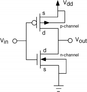
The fundamental issue presented is the perception that logic gates in a circuit seem to generate power from nothing, which contradicts the principles of physics. For instance, consider two NOT gates connected in series. It appears that the first...
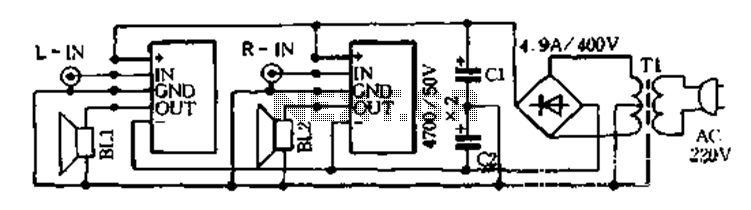
The D-200W module features a unique design that includes overload, overvoltage, overheating, short circuit, and reverse polarity protection, as well as shock protection for various speakers. The module employs a synchronous dynamic bias circuit to minimize static power consumption,...
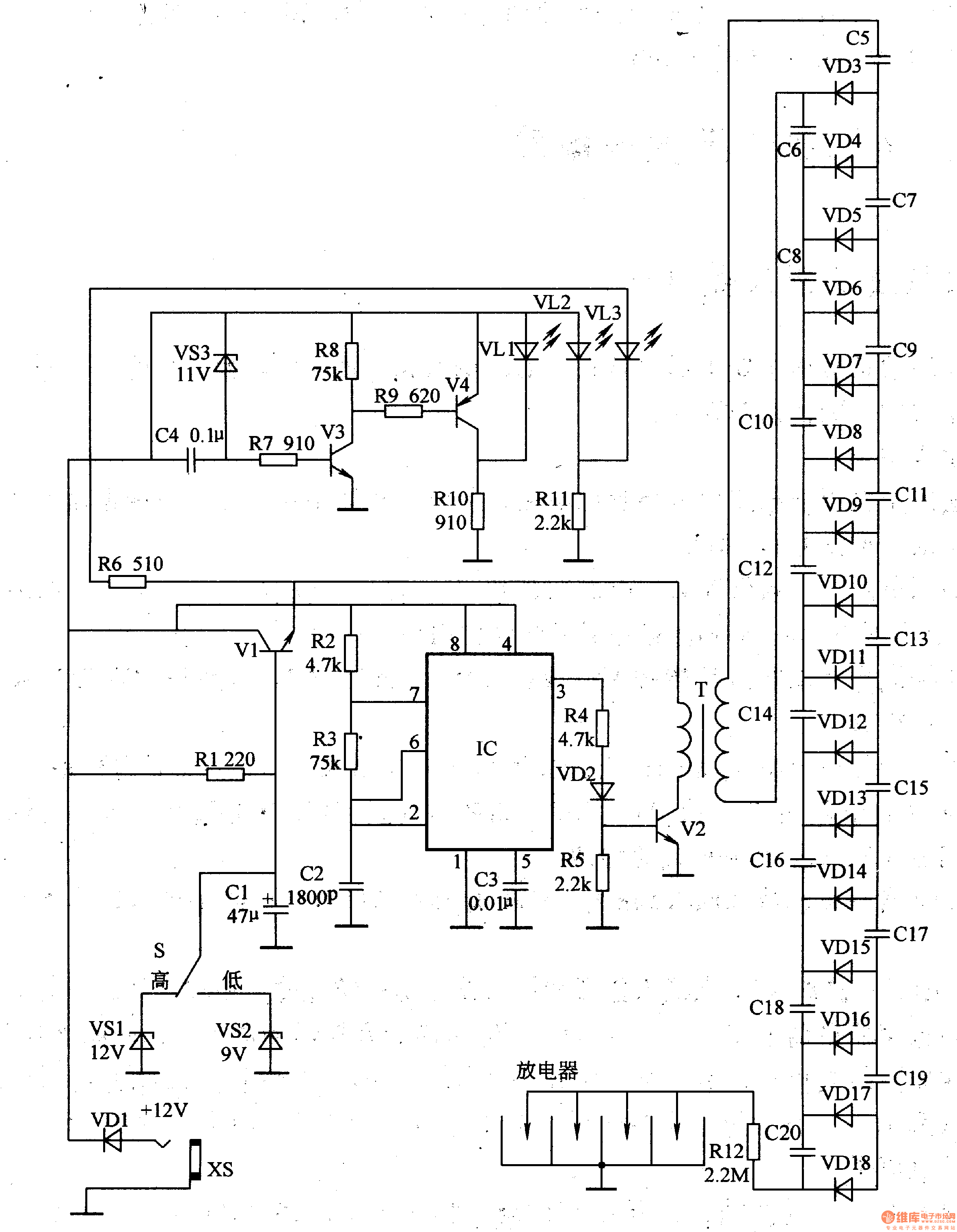
This negative oxygen ion generator circuit consists of a steady voltage power supply circuit, an under-voltage detection indication circuit, a high-frequency oscillator, and a high-voltage generator circuit, as illustrated in figure 9-113. The steady voltage power supply circuit is...
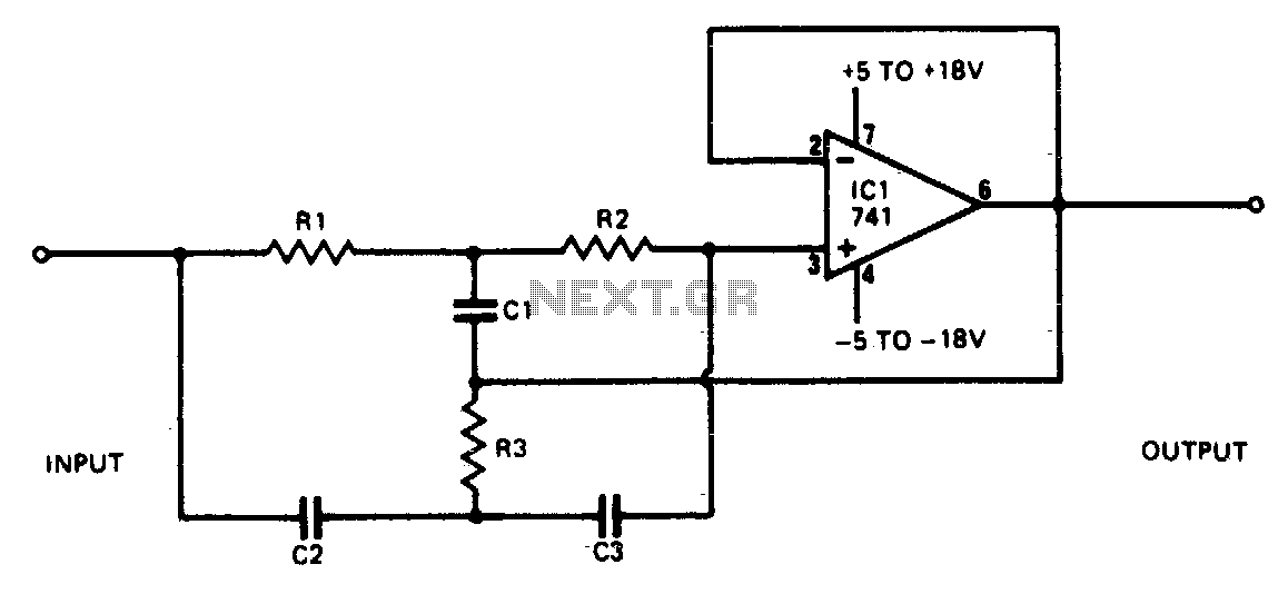
This narrowband filter utilizing the 741 operational amplifier can achieve a rejection level of up to 60 dB. By employing resistors with a value of 100 K ohms and capacitors of 320 pF, the circuit effectively rejects frequencies at...
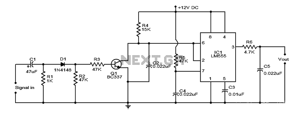
This document provides an overview of a simple circuit diagram for frequency (F and V) voltage conversion. It describes a digital frequency meter circuit primarily based on the LM555 timer IC, which is commonly used in various applications, including...
This perspective is not entirely incorrect, as the functioning of FM detectors is often considered enigmatic. The ratio detector is used to understand its operation, but without... FM detectors are critical components in communication systems, particularly in frequency modulation (FM)...