
Negative oxygen ion generator 1
The negative oxygen ion generator circuit is designed to produce negative ions, which can enhance air quality by neutralizing pollutants and allergens. The steady voltage power supply circuit ensures that the system operates reliably by maintaining a consistent voltage level. Diode VD1 rectifies the input voltage, while voltage regulator V1 stabilizes the output voltage, preventing fluctuations that could affect the performance of the circuit. The steady voltage diodes VS1 and VS2 are used to provide additional voltage regulation and protection against voltage spikes.
The ionization selection switch S allows the user to control the ionization process, enabling or disabling the generation of negative ions as needed. The power supply indication LED VL2 serves as a visual indicator, confirming that the circuit is powered and functioning correctly. The peripheral resistor-capacitor components work in conjunction with the aforementioned elements to filter noise and stabilize the circuit operation.
The under-voltage detection circuit plays a critical role in safeguarding the device from operating under insufficient voltage conditions. Transistors V3 and V4 are configured to monitor the voltage levels, and when the voltage drops below a predetermined threshold, steady voltage diode VS3 activates the under-voltage indication LED VL1. This LED serves as a warning signal, alerting the user to the low voltage condition that may compromise the operation of the ion generator.
The high-frequency oscillator and high-voltage generator circuit are essential for generating the necessary high voltage required for ionization. The oscillator produces a high-frequency signal that is then amplified by the high-voltage generator, enabling the circuit to create the electric field necessary for the ionization process. This combination of components ensures that the negative oxygen ions are produced efficiently and effectively, contributing to improved air quality in the surrounding environment.
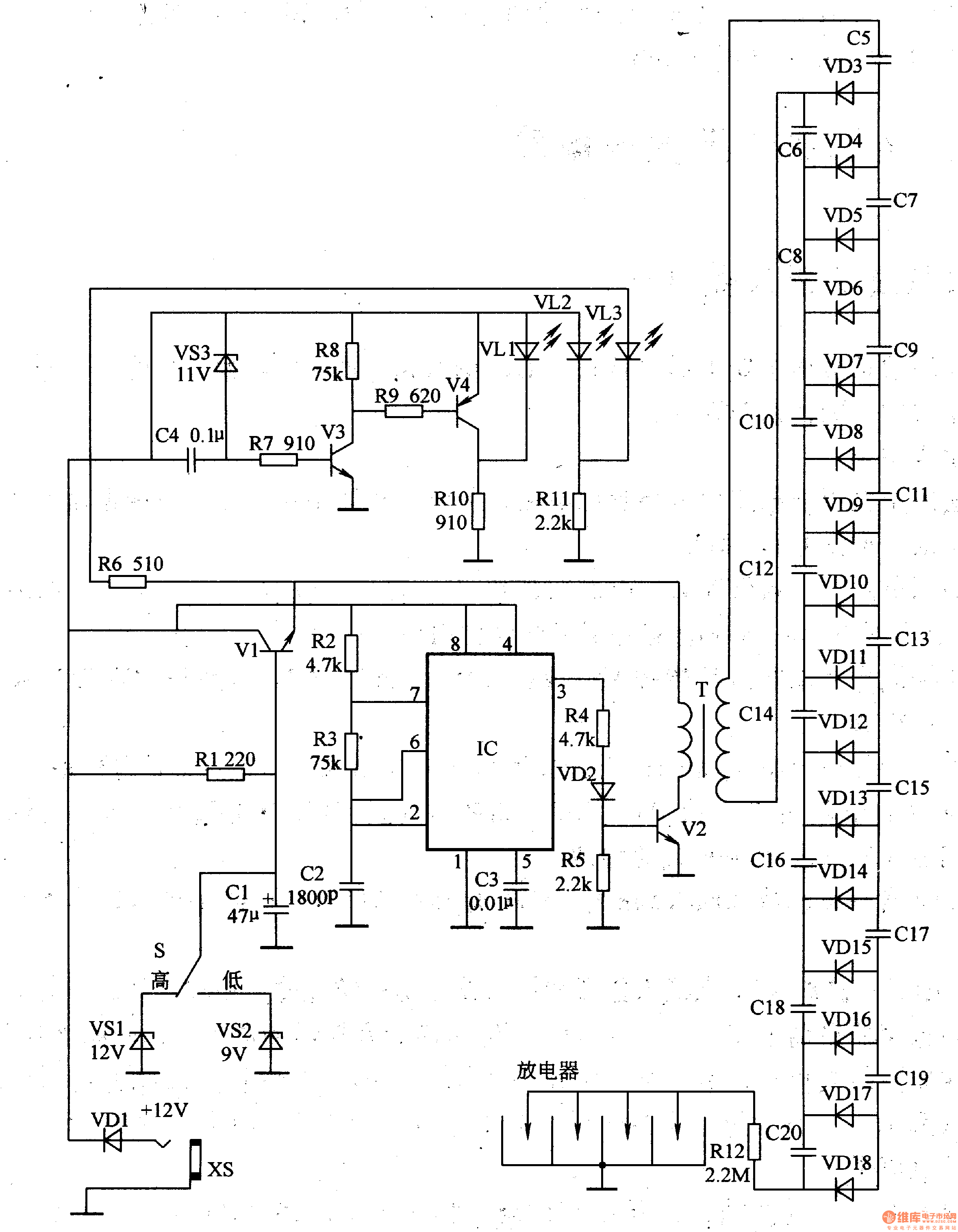
Overall, this negative oxygen ion generator circuit is a comprehensive design that integrates multiple functional components to achieve its objective of generating negative ions while incorporating safety features to prevent low voltage operation.This negative oxygen ion generator circuit is composed of power supply steady voltage circuit, under voltage detection indication circuit, high frequency oscillator and high voltage generator circuit, it is shown in the figure 9-113. The power supply steady voltage circuit is made of diode VD1, power supply regulator V1, steady voltage diodes VS1,
VS2, ionization selection switch S, power supply indication LED VL2 and peripheral resistor capacitor components. The under voltage detection indication circuit consists of transistors V3, V4, steady voltage diode VS3, under voltage indication LED VL1 and peripheral resistor capacitor components.
🔗 External reference
Related Circuits
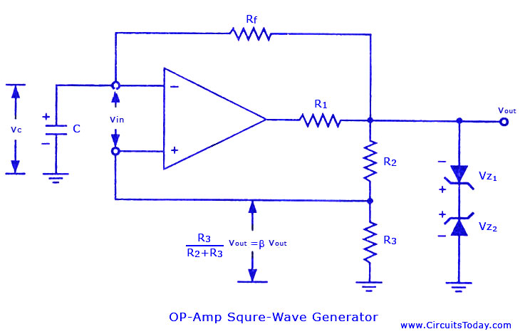
Non-sinusoidal waveform generators are also referred to as relaxation oscillators. The op-amp relaxation oscillator depicted in the figure functions as a square wave generator. Generally, square waves are relatively simple to generate. Similar to the UJT relaxation oscillator, the...
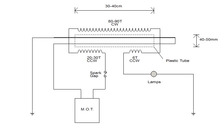
The user intends to purchase a transformer to operate with a 12V battery; however, the transformer in question differs from the one utilized by the user romerouk from Overunity. The circuit design involves a transformer specifically engineered for low-voltage applications,...
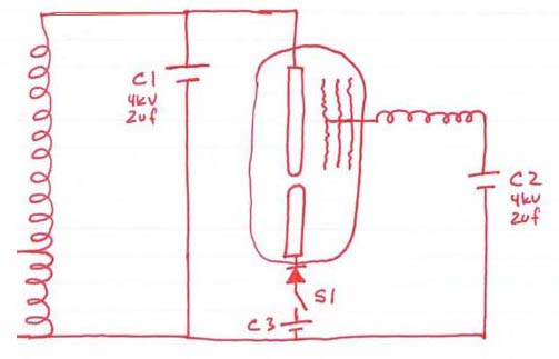
This was not simply shorting out a capacitor through the coil or the tube. However, there is a misunderstanding regarding the functionality of the tube. A discharge is not expected from the low voltage rod to capacitor C2. It...
Neon glow lamps can be utilized solely for their voltage/current characteristics rather than for illumination. These lamps are electrically similar to diacs; no current flows through them when the voltage is below a trigger value (approximately 70V for neon...
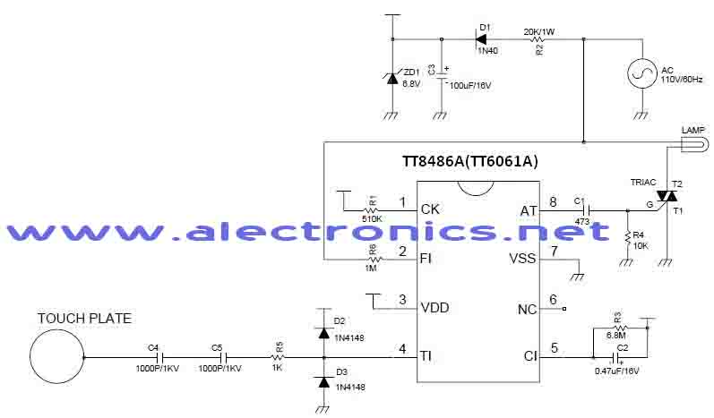
A simple dimmer circuit can be constructed using the CMOS ICs TT8486A and TT6061A, allowing control over the intensity of an incandescent lamp through a touch contact. This electronic touch dimmer can increase the brightness of incandescent lamps in...
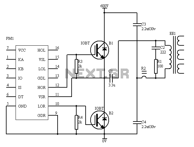
The PM4040F is utilized in switching power supply applications for medium power ranges. It is designed to drive power supplies between 200W and 800W, as illustrated in the accompanying bridge circuit. For power applications below 1000W, an alternative circuit...
Warning: include(partials/cookie-banner.php): Failed to open stream: Permission denied in /var/www/html/nextgr/view-circuit.php on line 713
Warning: include(): Failed opening 'partials/cookie-banner.php' for inclusion (include_path='.:/usr/share/php') in /var/www/html/nextgr/view-circuit.php on line 713