
IperCODE - HowTo Build a Remote Control Using Rolling Code
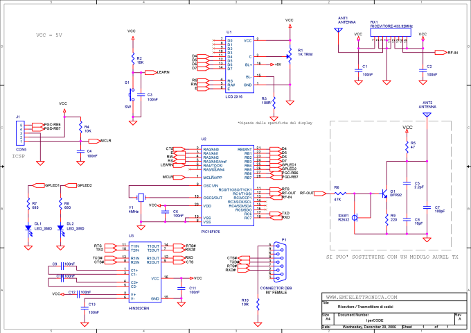
The IperCODE project incorporates a microcontroller to facilitate the acquisition and processing of the rolling code signals. The system typically begins with a remote control that transmits a unique rolling code, which is received by a dedicated RF module. The received signal is then processed by the microcontroller, which decodes the rolling code and prepares it for further actions.
For data transmission, the microcontroller interfaces with an RS232 module, allowing the decoded code to be sent to a connected device, such as a computer or another microcontroller. This feature is particularly useful for applications that require logging or monitoring of the received codes.
The project also includes a 16x2 LCD display, which serves as a user interface. The microcontroller drives the display to show the received rolling code in real-time, providing immediate feedback to the user. This display functionality can be enhanced with additional features, such as scrolling text or error messages, depending on the complexity of the implementation.
Overall, the IperCODE project serves as an excellent educational tool for understanding remote control systems, rolling code technology, and serial communication protocols, while also providing practical experience in microcontroller programming and interfacing with peripheral devices.IperCODE is a didactic project, with which it is possible to build a remote control acquisition system, based on the rolling code and to have the possibility to transmit the received code on RS232 serial port, to visualize it on the 16X2 display or to reproduce it 🔗 External reference
Related Circuits
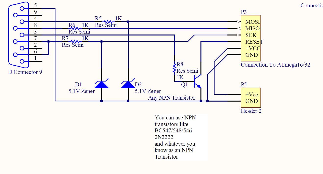
ISP programmer with circuit diagram for AVR Atmega32 microcontroller. This ISP burner circuit is an adaptation of the Pony programmer and uses PonyProg software. The ISP (In-System Programming) programmer designed for the AVR Atmega32 microcontroller facilitates the programming of the...
This circuit controls resistive and inductive loads up to 2,500W. Its main functional device is an integrated phase control circuit - Siemens TLE3103. It contains its own power supply, a zero voltage crossing detector circuit and a logic driver....
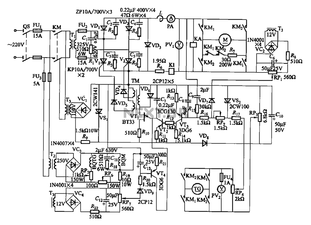
The circuit encompasses a main circuit, a trigger circuit, speed negative feedback, negative feedback differential voltage, a current cut-off circuit, loss of field protection, and other components. Given that the motor power is small (1.1 kW), a single-phase circuit...
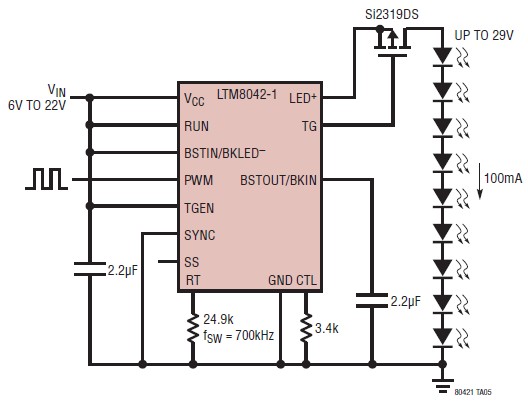
The LTM8042 integrates a boost power topology with a unique current loop to function as a constant-current source. The PWM input allows for LED dimming ratios of up to 3000:1, while analog dimming can be achieved with a single...
Figure 2-33 (a) illustrates the schematic diagram of a robot approaching an object. When no objects are detected in front of the robot, it moves forward in a straight line. If an object is detected on the left or...
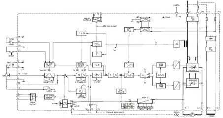
This figure represents the 4Q2 DC Motor Speed Controller Circuit Block Diagram, designed for comprehensive control of conventional shunt-wound and permanent magnet motors with a capacity of up to 75 kW, as specified in the datasheet. This type of...