
What is analog to digital converter ADC using LM324 IC
The Analog to Digital Conversion (ADC) process is critical in various electronic applications, facilitating the interface between analog signals and digital systems. The ADC circuit described employs the LM324 operational amplifier, which is advantageous due to its multiple op-amps integrated into a single package, allowing for compact design and reduced component count.
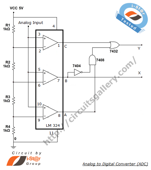
In this 2-bit ADC configuration, the input analog voltage is first processed through a potential divider network, which scales the voltage to appropriate levels for comparison. The LM324 comparators are configured to compare the scaled analog voltage against reference voltage levels, which correspond to the thresholds for the different binary outputs.
The reference voltages can be set using a precision voltage reference or derived from the power supply, ensuring accuracy in the conversion process. Once the analog voltage is compared, the output of the LM324 will transition between high and low states, depending on whether the input voltage exceeds the reference levels.
The outputs from the comparators are then fed into a combinational logic circuit, which consists of three logic gates. This arrangement is designed to encode the comparator outputs into a 2-bit binary format, effectively translating the analog input into a digital representation. The logic gates perform the necessary operations to produce the desired binary outputs of 00, 01, 10, and 11, corresponding to the four distinct levels of the input analog voltage.
The resolution of this ADC circuit is limited to 2 bits, allowing for 4 discrete levels of output. This resolution is sufficient for applications that do not require high precision, but it is essential to note that increasing the number of bits in the ADC would enhance the resolution, providing a finer granularity of the analog input representation.
In summary, the described ADC circuit efficiently converts an analog voltage into a digital signal using the LM324 comparator IC, a potential divider, and combinational logic, demonstrating a practical approach to analog-to-digital conversion while maintaining simplicity and effectiveness in design.The process of converting an analog voltage into an equivalent digital signal is known as Analog to Digital Conversion, abbreviated as ADC. An ADC is an electronic circuit which converts its analog input to corresponding binary value. The output depends up on the coding scheme followed in the ADC circuit. For example Analog value may convert to Gra y code, excess 3 code and so on. Analog to Digital converter ICs are also available to do this operation. Which reduce the circuit complexity such that a single IC capable of doing Analog to Digital Conversion. The circuit below shows a 2 bit ADC circuit using LM324 comparator IC. A potential divider network and some combinational circuits are used for making this simple ADC. LM324 best suited for Analog to Digital Converters because it has four embedded op amps, it require Vcc (5V) and ground only.
No need of -Vcc like 741 op amp. To represent 4 states in binary, only 2 bits are needed, so we are using a digital combinational code converter circuit with 3 logic gates. Thus it is possible to get binary outputs like 00, 01, 10, and 11. The term Resolution is used to describe the accuracy of ADC, resolution means the number of distinct values that ADC can generate over the range of analog values.
🔗 External reference
Related Circuits
Powering up twin digital Sony DSC-V1 cameras simultaneously can achieve remarkable synchronization within milliseconds. This is accomplished through the use of dual Sony wired remotes that short the ACC port LANC signal conductor to the ACC port ground. Further...
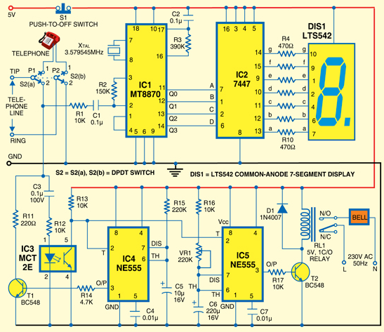
A simple calling bell circuit designed for small offices to summon the office boy using an existing intercom system. The office boy can be called from up to nine locations equipped with extension lines. The system connects to a...
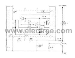
If you have ever used a 12V flasher relay system, typically a mechanical type, for general automotive applications, today we will attempt to build a 12V flasher relay circuit. The 12V flasher relay circuit is a crucial component in automotive...
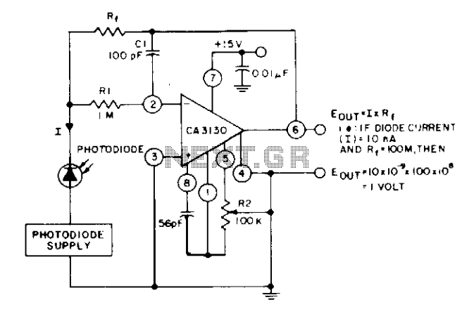
The circuit utilizes three CA3130 BiMOS operational amplifiers in an application that is sensitive to sub-picoampere input currents. It provides a ground-referenced output voltage that is proportional to the input current flowing through the photodiode. The circuit design employs three...
A standard serial interfacing for PC, RS232C, requires negative logic, i.e., logic 1 is -3V to -12V and logic 0 is +3V to +12V. To convert a TTL logic, say, TxD and RxD pins of the uC chips, thus...
This circuit is designed for precise centigrade temperature measurement. It features a transmitter section that converts the sensor's output voltage, which is proportional to the measured temperature, into frequency. The output frequency bursts are transmitted through the mains supply...