
IR Bug

The circuit described comprises several key components that work in synergy to achieve the desired functionality. The melody generator receives an amplified signal, which is essential for producing a clear and discernible output. Resistor R5 plays a crucial role in ensuring that the signal is appropriately conditioned before it reaches the melody generator. The LM386 audio amplifier is chosen for its low power consumption and sufficient gain, making it ideal for this application. Variable resistor VR1 allows for user-adjustable volume control, enhancing the usability of the circuit.
Capacitor C3 is strategically placed to decouple the positive rail, which helps to stabilize the power supply and minimize noise that could interfere with the performance of the audio amplifier. The combination of C4 and R7 serves to filter out high-frequency noise, ensuring that only the desired frequencies are amplified and sent to the loudspeaker. This filtering is critical in maintaining sound quality and preventing distortion.
The assembly on a general-purpose PCB simplifies the construction process, making it accessible for prototyping and educational purposes. The inclusion of pin configurations for the LM386, BC547, and UM66 allows for easy reference during assembly and troubleshooting.
The circuit's operation hinges on the conversion of IR signal pulse trains into audible notes, a process facilitated by the melody generator. The use of switch S1 for power control and LED1 for power indication enhances the user interface, providing clear feedback on the circuit's operational status.
Furthermore, the voltage stabilizer formed by resistor R4 and zener diode ZD2 ensures that the small signal preamplifier circuit receives a consistent voltage supply, which is vital for maintaining performance across varying conditions. The primary sensing element, IR LED1, is responsible for detecting the IR signals, which are subsequently amplified by the NPN transistors T1. This amplification stage is crucial for ensuring that the detected signals are strong enough for further processing, ultimately leading to the generation of sound output through the loudspeaker.The amplified signal is fed to the melody generator via resistor R5. The output of the melody generator is fed to LM386 low-power audio amplifier (IC2) via variable resistor VR1, which works as the volume control. The loudspeaker sounds to indicate a voltage gain of 20, ` which is sufficient for this application. Capacit or C3 is used for decoupling of the positive rail and the R-C combination network comprising C4 and R7 bypasses high frequency to ground. The circuit can be easily wired on a general-purpose PCB. Pin configurations of IC LM386, transistor BC547 and melody generator UM66 are shown. principle, converts the IR signal pulse trains into noticeable aural notes. S1 is used to switch on/off mains power and LED1 indicates power on. ` Resistor R4 and zener diode ZD2 form a low-current voltage stabiliser for providing steady 5. 1V DC to the small signal preamplifier circuit. IR LED1 is the main sensing element. The IR signal detected by IR LED1 is amplified by npn transistors T1. 🔗 External reference
Related Circuits
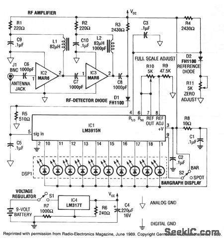
This RF detector can locate low-power transmitters (bugs) that are hidden from sight. It can sense the presence of a 1-mW transmitter at a distance of 20 feet, which is sensitive enough to detect the smallest bug. As the...

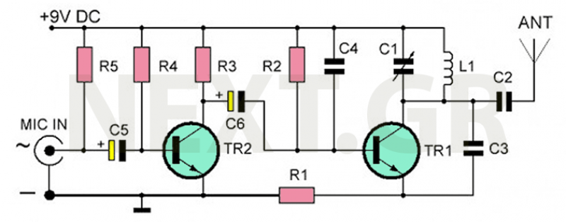
This circuit represents an FM transmitter, also referred to as an FM Bug, which consists of 18 essential components for optimal functionality. The circuit begins with an electret microphone on the far left side, and the signal flows electrically...
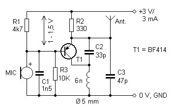
The presented FM transmitter circuit is constructed using BF414, BF324, or BF606 transistors. It features a 30 cm antenna that provides a range of approximately 30 meters indoors and even greater range outdoors. The power supply consists of two...

This is a basic telephone broadcaster or transmitter designed for eavesdropping on telephone conversations. The circuit can also function as a wireless telephone amplifier. A key feature of this phone transmitter is that it derives its power directly from...

This is a simple RF bug detector designed to identify spy bugs, capable of operating up to 2 GHz. Below are some essential components required for this circuit. The RF bug detector circuit functions by utilizing radio frequency signals...
The recommended transmitter is straightforward to construct and suitable for beginners. Despite its simple design and compact size, it delivers remarkable performance. It operates for 12-15 hours on a 9-volt battery and has a transmission range of 100 to...