
Micro Transmitter Bug
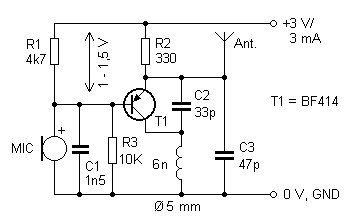
The FM transmitter circuit utilizes a common emitter configuration, where the chosen transistor amplifies the audio signal for transmission. The BF414, BF324, and BF606 transistors are suitable for this application due to their high-frequency response and low noise characteristics, making them ideal for FM modulation. The 30 cm antenna is designed to be resonant at the desired frequency of operation, which allows for effective radiating of the modulated signal.
The power supply design, utilizing two AAA batteries, provides a compact and portable power source with a nominal voltage of 2.75 V, ensuring that the circuit operates efficiently without excessive power consumption. The inclusion of the 10 kΩ resistor in parallel with the 1.5 pF capacitor forms a high-pass filter that helps to block low-frequency noise and stabilize the audio signal when connected to external devices.
The requirement to adjust the computer's sound output to 35% capacity is an important consideration for avoiding distortion, particularly in audio applications where signal integrity is paramount. The shielding implemented in the design serves to minimize electromagnetic interference, thereby improving the overall stability and performance of the transmitter.
The coil, consisting of five turns of enameled copper wire with a diameter of 5 mm, is critical for creating the oscillating magnetic field necessary for RF transmission. The inductance of this coil, combined with the capacitance of the circuit, determines the resonant frequency, which is crucial for effective FM broadcasting. Proper tuning of the circuit may be necessary to achieve optimal performance, which can be done by adjusting the coil turns or using variable capacitors in conjunction with the fixed capacitors.
Overall, this FM transmitter design is a practical solution for short-range audio transmission, suitable for various applications such as personal broadcasting or audio demonstrations.Presented FM transmitter bug is built using BF414 / BF324 / BF606 transistor. The 30cm antenna has a range of about 30m in the building, more in the open field. Power supply 2x AAA batteries have been used with voltage of 2.75 V. I added resistor 10K in parallel with 1.5pF capacitor so that the system works well when connected to an external source (mp3 player / computer). On the computer I had to reduce sound to about 35% of capacity, so that I do not have clipping. I managed to improve transmitter stability with simple shielding. The coil is 5 turns of enameled copper wire wound on 1 mm ? = 5 mm 🔗 External reference
Related Circuits
This project was a final assignment for an optics class (EE 134) at Stanford University. It was an open-ended task aimed at creating a fully functioning laser microphone. The class focused on demonstrating optics and photonics in the laboratory...

This document discusses the use of small microcontrollers, such as those from the PIC and Atmel series, which typically operate at 5V and require less than 100mA for complete system functionality. Some PICs can function at lower voltages, such...
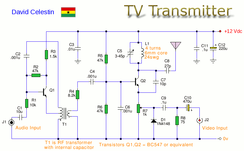
This is an analogue TV transmitter. Sound modulation is FM with a 5.5 MHz carrier, and video transmission uses PAL. The frequency is adjustable via C5 and tunes from 54 to 216 MHz with the components shown. This transmitter...
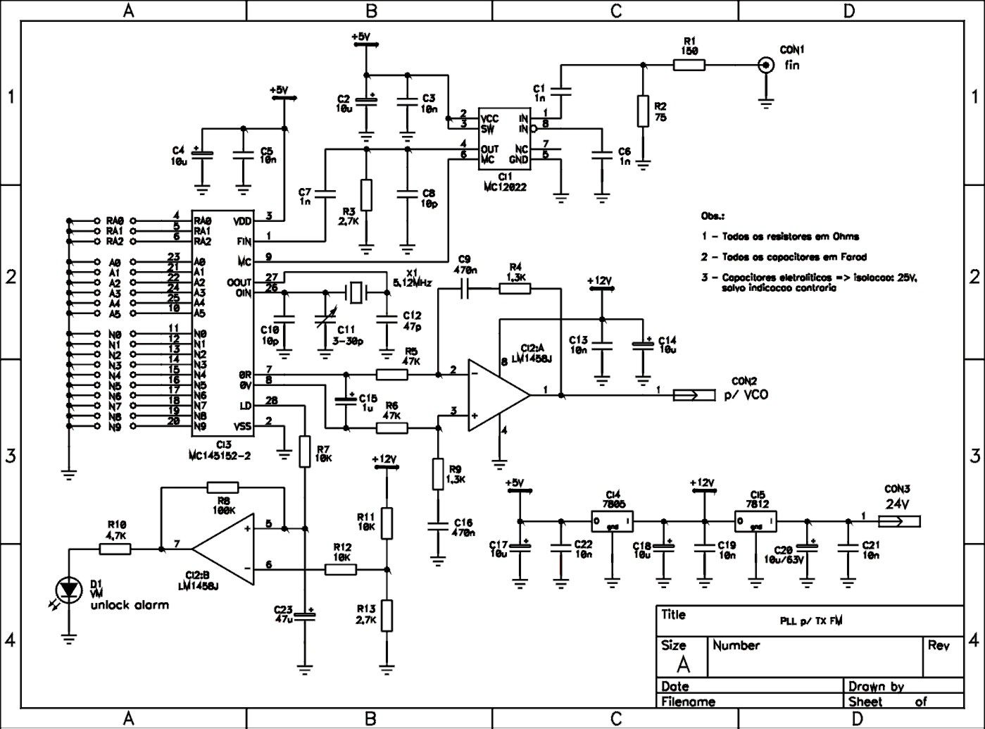
This is a schematic of a synthesized Phase-Locked Loop (PLL) for a low-power FM transmitter. It can also be utilized with other circuits, provided that the loop filter response, components, VCO tank circuit, and appropriate thumbswitch programming keys and...
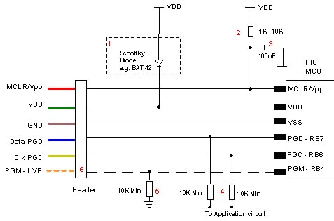
Microchip does not recommend any specific circuit for In-Circuit Serial Programming (ICSP). Various diagrams exist for different tools, such as Pro Mate and PICKit2, which feature similar circuitry with minor variations. Some schematics may suggest resistor values that are...
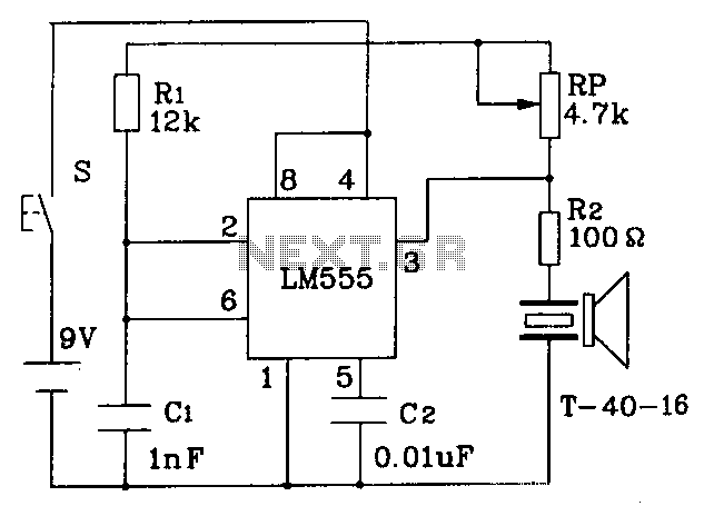
The circuit operates at a distance of 3 feet from the oscillating pulse output of a 555 timer generating a 40kHz signal, driving a T-40-16 transducer to emit ultrasonic signals at the same frequency. The circuit is powered by...