
IR DETECTOR CIRCUIT
The described circuit operates as a basic IR signal detection system. The IR phototransistor Q1 is sensitive to infrared light emitted by remote control devices. When the remote control is activated, it emits a modulated IR signal, which the phototransistor detects. The phototransistor is typically connected in a common emitter configuration, allowing it to convert the received IR light into a small current.
The output current from Q1 is insufficient to drive an LED directly, hence the inclusion of the PNP transistor Q2. When Q1 detects the IR signal, it generates a collector current that flows into the base of Q2. This base current turns Q2 on, allowing a larger current to flow from its collector to emitter, thus powering LED1. The LED lights up as a visual indicator that an IR signal has been successfully received.
Proper biasing of both transistors is essential for the circuit's functionality. Resistors may be used in series with the phototransistor and the base of the PNP transistor to ensure they operate within their specified ranges. Additionally, a current-limiting resistor should be placed in series with LED1 to prevent excessive current from damaging it.
This circuit can be used in various applications, including remote control verification systems, IR signal testing devices, and simple home automation projects, where it is necessary to confirm the operation of remote control devices. The simplicity of the design makes it suitable for educational purposes as well, demonstrating the principles of phototransistor operation and transistor amplification.The circuit uses an IR phototransistor, Q1, to detect a remote control`s IR output signal. A PNP transistor, Q2, then amplifies Q1`s output and lights LED1. That indicates that an infrared signal has been detected by the phototransistor, or in other words, that your remote control works. 🔗 External reference
Related Circuits
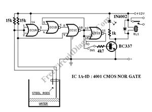
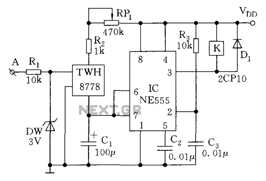
The circuit consists of a 555 timer IC configured as a multivibrator, which operates with two probes to measure the water level. When the capacitance between the probes indicates a high water level, the output from the 555 timer...
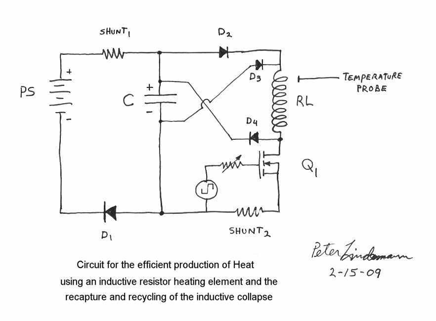
Rosemary's original test circuit is shown in the article she tried to have published in a refereed scientific journal, but the submission was always rejected. In the last 5 months, I have had extensive email correspondence, and numerous telephone...
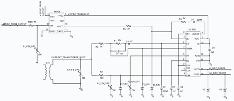
The UC3825 IC, manufactured by Texas Instruments, is a high-speed pulse width modulation (PWM) controller that serves as the central processor for a DC/DC converter control circuit. This circuit primarily consists of three integrated circuits: the UC3825BN, ISO124, and...
Assistance is needed to understand a schematic. Most components are clear, except for the triangular symbols which are likely operational amplifiers (op-amps). Clarification is required on their implementation and arrangement. The current diagram is intended for testing with a...
The count switching circuit consists of an electronic switch and a pulse delay circuit for control. The count switching circuit is designed to manage the switching of signals in a controlled manner. The electronic switch serves as the primary component...
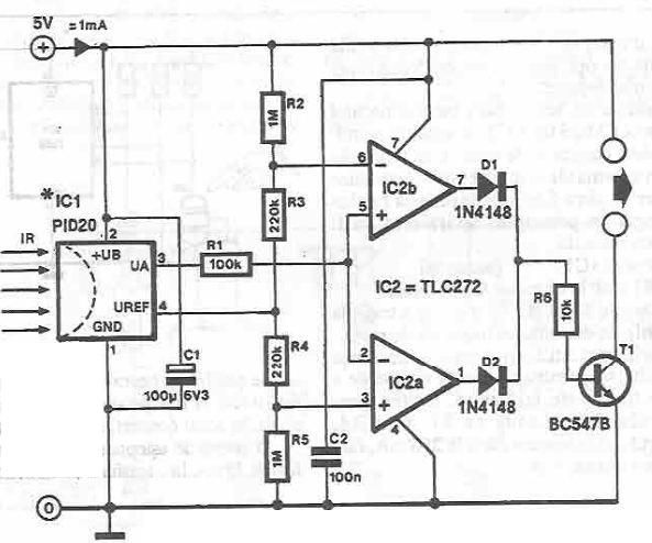
This infrared detector circuit utilizes the PID20 integrated circuit manufactured by Siemens, which converts thermal radiation into electrical impulses. It includes an operational amplifier and several electronic components. The output signal at pin 3 is compared to a reference...