
Robot Beacon with PIC12C508A
The PIC12C508A is a one-time programmable (OTP) microcontroller, suitable for various embedded applications. Its architecture allows for a maximum of 512 program memory locations, with a limitation on the use of CALL instructions due to the memory addressing constraints. The device operates in conjunction with the PIC16F84, which serves as a development platform due to its re-programmable nature. This hybrid approach allows for iterative programming and testing without the high costs associated with multiple OTP chips.
During the development phase, the PIC16F84 can be programmed and debugged using standard development tools such as MPASM and ICProg. The transition from the 16F84 to the PIC12C508A involves ensuring that the common instruction set is utilized to maintain compatibility. The programming process requires careful management of memory locations, particularly avoiding the use of CALL instructions for addresses above 0FFh. Instead, the use of GOTO instructions and the strategic placement of NOPs can facilitate the integration of new routines without disrupting existing functionality.
The PIC12C508A's pin configuration mirrors that of the PIC16F84, particularly in the context of GPIO ports. Lines GP0 to GP5 on the PIC12C508A correspond to RB0 to RB5 on the PIC16F84, enhancing the ease of porting designs between the two devices. Special attention must be paid to GP3 (RB3), which is designated as an input-only line, typically used for interfacing with external components such as push-button switches.
In summary, while the PIC12C508A presents challenges in terms of its one-time programmability, it can be effectively utilized in conjunction with the PIC16F84 to streamline the development process, allowing for efficient testing and final programming of embedded applications.We hold the "first rights" to the presentation of this approach and the best part is: "It's FREE!" The PIC12C508A is one of the most amazing devices but because it does not come in a low-cost re-programmable form, it has never been presented in a "designers article." It is a one-time programmable device (OTP) and once it is programmed, it cannot be re-programmed. To develop with this chip is not an economical decision as it may take 30 to 100 modifications before you are completely happy with the operation of the software.
That's 99 wasted chips! The only way to carry out experimentation is with the EPROM version (window version). These carry the part number PIC12C508A-JW and are about 10 times the cost of a normal PIC12C508A. To remove the program, they must be erased under an ultra-violet lamp for about 20 minutes. When you are in the process of developing, this time-delay is very annoying and it usually takes about 10 units to keep the development process active. Adding up the costs, makes this process slow, cumbersome and costly. We have got around this problem by using a PIC16F84 to hold the development program and when you are completely satisfied with the operation, the EXACT SAME program is burnt into a PIC12C508A.
All you have to do is select "12C508A" in the chip list on MPASM and the program will be assembled with a .hex file to suit a 508A. Click on ICProg, select 508A as the chip to be programmed, insert a 508A into the Multi Chip Programmer and the program will be burnt into the 8 pin chip.
The .hex files for the two chips are entirely different as the "core" of each is different, but that does not involve us. The programming instructions are the "same" and the circuit-operation is the same. The secret to this approach is to use only the instructions and files that are common to both chips. Fortunately nearly all the instructions for the 16F84 can be used by the 508A and nearly all the files are common.
The table above shows the similarities etc. The PIC12C508A chip is theoretically a One Time Programmable device, but it can be re-burnt, providing a number of points are remembered. Any location can be re-burnt "down." This means any bit in any location can be changed from a "1" to "0." This gives a wide range of possibilities for any byte but it will be very rare that a byte will need to be changed like this.
The other method is to place the new routine after the old program and "NOP" out the old program. This is easily done by counting the bytes in the old program and placing the same number of NOP's above the new program you are burning. Add say an extra 3 - 10 NOPs just to be sure that no old instructions remain. The micro will quickly run though the NOPs before coming to the new program, each time the project is turned on and everything will run as before.
There are only two things you have to be aware of. The interrupt vector (location 004) will not be available. The program must not have any CALL instructions (if you have any locations higher than 0FFh - that need to be "jumped to" via a CALL instruction). The PIC12C508A has 1FFh locations (512) - minus the last location as it is the oscillator calibration byte and is not available for a program instruction.
CALL instructions only work to the first 0FFh (256) locations (half the memory of a 508A). One of the solutions is to place sub-routines in Main and use only GOTO instructions. This may increase the length of the program but it is one way to get around the problem. If the program does not work perfectly on the second burn, it can be NOP'ed and the new program added below, until the whole memory has been used. They are about 95% compatible and all the in/out lines of the 508A are identical to port B lines on the F84.
In/out lines GP0 to GP5 on the PIC12C508A are common to in/out lines RB0 to RB5 for the PIC16F84. The only thing to remember is line GP3 (RB3). It is an input-only line and this is where you normally place a push-button or some other input device. 🔗 External reference
Related Circuits
The beacon is currently utilizing a simple Continuous Wave (CW) keying QRSS3 at a frequency of 10140.020 kHz, with a power output of 20 milliwatts. The PIC program used is PicBeacon developed by Ik2pcb. The concept for this beacon...
This is an attempt to create a simple and compact photovore. Although it may not be visually appealing, it serves as a good starting point for beginners. It is a personal version of the Dozer photovore. The latest robot...
A robot has been designed and built to vacuum the floor of a room or area autonomously, requiring only the initial activation by a user. This project addresses the demand for an affordable and user-friendly product that can independently...
In this project, an ATMEGA16 microcontroller operating at 16MHz will be utilized. To distinguish this project from others, a unique feature has been incorporated: a battery monitoring system. Many robots operate on new or freshly recharged batteries, and if...
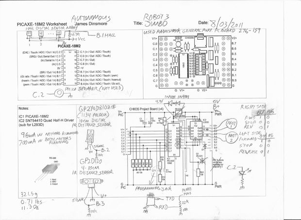
This is an autonomous robot designed to explore the interfacing of various sensors with a PICAXE processor. Its mission is to search for a magnet. The autonomous robot operates based on a microcontroller architecture centered around the PICAXE processor, which...
A remote control car can be operated over the internet or wirelessly from a laptop up to 500 meters away. It features a live-feed network camera for driving without line of sight and a horn for signaling. The project...