
IR Music Transmitter and Reciever
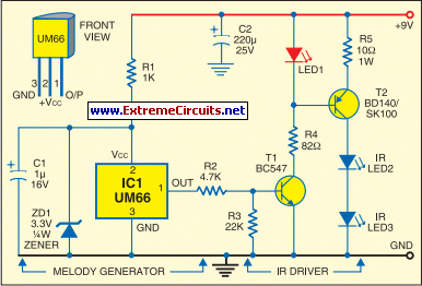
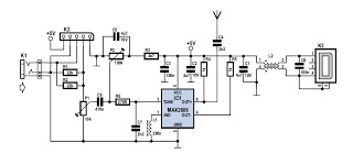
The IR music transmitter circuit is primarily centered around the UM66 melody generator, which is capable of producing a variety of musical notes. This IC is designed to operate with minimal external components, making it an efficient choice for audio applications. The output from the UM66 is fed into a driver stage composed of transistors T1 and T2, which amplify the signal before it is transmitted as infrared light through the IR LEDs. The modulation of the red LED (LED1) provides a visual cue that the circuit is functioning and that musical notes are being generated.
On the receiving end, the IR music receiver circuit is designed to capture the infrared signals emitted by the transmitter. The phototransistor L14F1 (T3) plays a crucial role in detecting the IR light and converting it back into an electrical signal. This signal is then processed by the µA741 operational amplifier, which amplifies the audio signal. The gain of the amplifier can be adjusted using the variable resistor VR1, allowing for fine-tuning of the volume before the signal is sent to the LM386 audio amplifier.
The LM386 is a low-voltage audio amplifier that is well-suited for driving small speakers. The output from the LM386 is directed to the loudspeaker LS1, enabling the audible playback of the melody. The variable resistor VR2 allows for volume control, providing the user with the ability to adjust the sound level to their preference. The overall design of the circuit emphasizes simplicity and efficiency, making it an accessible project for those interested in audio electronics and infrared communication. When the power supply is disconnected, the entire circuit ceases operation, ensuring that the melody generation is halted.Using this circuit, audio musical notes can be generated and heard up to a distance of 10 metres. The circuit can be divided into two parts: IR music transmitter and receiver. The IR music transmitter works off a 9V battery, while the IR music receiver works off regulated 9V to 12V. First diagram shows the circuit of the IR music transmitter. It u ses popular melody generator IC UM66 (IC1) that can continuously generate musical tones. The output of IC1 is fed to the IR driver stage (built across the transistors T1 and T2) to get the maximum range. Here the red LED (LED1) flickers according to the musical tones generated by UM66 IC, indicating modulation.
IR LED2 and LED3 are infrared transmitting LEDs. For maximum sound transmission these should be oriented towards IR photo-transistor L14F1 (T3). The IR music receiver uses popular op-amp IC µA741 and audio-frequency amplifier IC LM386 along with photo-transistor L14F1 and some discrete components (second diagram). The melody generated by IC UM66 is transmitted through IR LEDs, received by phototransistor ceived by phototransistor T3 and fed to pin 2 of IC µA741 (IC2).
Its gain can be varied using potmeter VR1. The output of IC µA741 is fed to IC LM386 (IC3) via capacitor C5 and potmeter VR2. The melody produced is heard through the receiver`s loudspeaker. Potmeter VR2 is used to control the volume of loudspeaker LS1 (8-ohm, 1W). Switching off the power supply stops melody generation. 🔗 External reference
Related Circuits

The circuit is basically a radio frequency (RF) oscillator that operates around 100 MHz. Audio picked up and amplified by the electret microphone is fed into the audio amplifier stage built around the first transistor. Output from the collector...
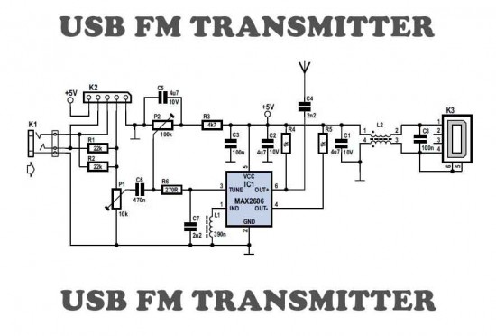
This is a simple USB FM transmitter designed to play audio files from an MP3 player or computer on a standard VHF FM radio. The USB FM transmitter operates by converting audio signals from a digital source, such as an...
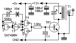
This is a very simple 5 watt CW TX based upon a TTL logic chip. There is just one "tricky" component and this is Cx. This component should have an impedance of about 10 - 50 ohms at the...
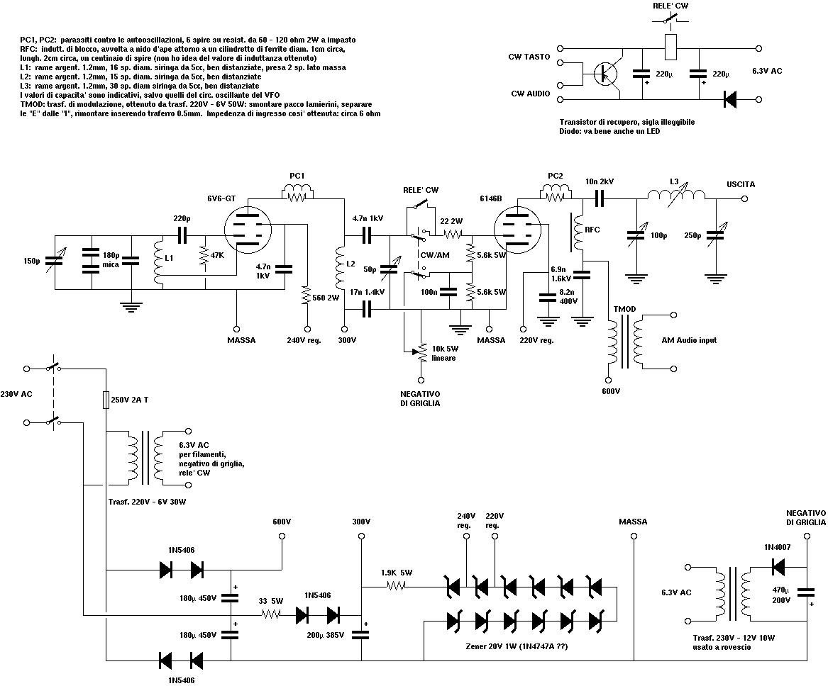
A copy from an old Italian magazine of amateur electronics proposed an add-on for tube receivers. The add-on was a simple one-tube short-wave transmitter leveraging the same power supply already available in the receiver. The project reported in that...
This MP3 player FM transmitter allows users to enjoy their music throughout their home. The transmitter circuit does not require any coils to be wound. When utilized in a vehicle, there is no need for a separate input to...

The transmitter for the wireless headphones is built around a CD4046 CMOS phase-locked loop, coupled with a driver transistor, and a pair of infrared LEDs. More: Although the CD4046 is comprised of two phase comparators, a voltage-controlled oscillator (or...