
PQY1 series magnetic disk control circuit control

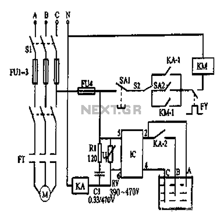
The LK16-5/31 master controller serves as the primary interface for the operator, allowing for precise control of the motor's operation through its various positions. Each of the seven handle positions corresponds to specific operational states, facilitating efficient management of the motor's direction and speed. The three upward positions enable the motor to perform lifting actions, while the three downward positions allow for controlled descent. The zero position acts as a neutral state, ensuring that the motor is deactivated when not in use.
The inclusion of limit switches SQ1 and SQ2 is crucial for ensuring safe operation. These switches detect the motor's position and prevent it from exceeding predetermined limits. When the motor reaches the upper or lower limit, the corresponding switch is activated, signaling the controller to halt the motor's movement, thereby preventing mechanical damage or failure.
The PQY1 Series magnetic control panel complements the master controller by providing additional functionality and safety features. It is designed to handle the electrical connections and control signals necessary for the operation of the motor and its associated components. The panel's layout is optimized for ease of use and accessibility, allowing operators to monitor and adjust settings quickly.
Furthermore, the system's parking brake modes enhance safety during operation. The organic mechanical parking brake mode engages a traditional mechanical brake system, ensuring the motor remains stationary when not in operation. The reverse parking brake mode provides an additional layer of safety by preventing unintended movement when the motor is in reverse, thereby protecting both the equipment and the operator.
Overall, this comprehensive control system is designed to ensure reliable and safe operation of the motor, with multiple features aimed at enhancing user control and preventing accidents. By LK16-5/31 type master controller and PQY1 Series Magnetic control panel consisting of a control circuit. Figure, SQ1, SQ2 the motor is, reverse limit switch. Master controll er handle SA has seven positions, in addition to the zero position, there are three rose and three fell block block. In addition to organic mechanical parking brake mode, there are reverse parking brake mode.
Related Circuits
This is a 25-watt basic power amplifier designed for ease of construction at a reasonable cost. It offers superior performance compared to standard STK module amplifiers commonly found in most mass-market stereo receivers produced today. The 25-watt basic power amplifier...
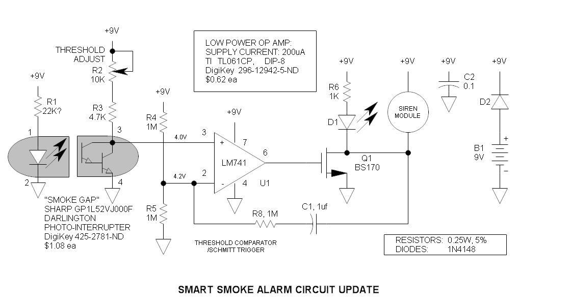
The original smoke alarm circuit has several issues that have left hobbyists and students dissatisfied. Instead of trying to resolve its numerous problems, an updated version has been created using the well-known LM741 op-amp. This new design is simpler,...
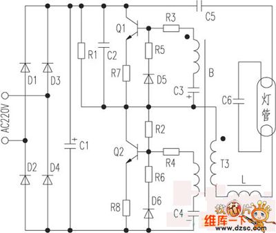
The saving lamp circuit features two main types: glass cover and exposed. The glass cover variants include three series: spherical, cylindrical, and processing types. The first two series consist of four variations: transparent, carved, engraved, and white. These lamps...
This is a circuit design for a temperature relay that can be used to signal a fire or monitor temperature set points. The adjustment of P1 is necessary to ensure that the base voltage of T1 is 0.5V lower...
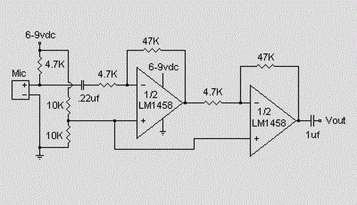
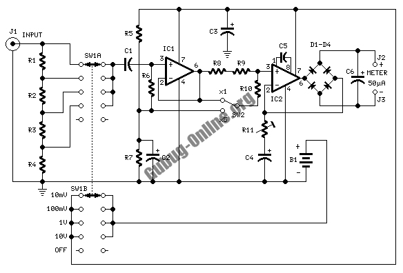
This is a simple preamplifier circuit designed for an electret condenser microphone, utilizing an LM1458 dual op-amp integrated circuit (IC). The circuit amplifies the audio signal from the condenser microphone, allowing it to be used as an input for...
An automatic water tank system is illustrated in the circuit diagram. The circuit employs a PSSR AC solid-state relay, which is a new type of solid-state relay designed for AC applications. Unlike traditional solid-state relays (SSR), this PSSR not...